Communication system for flexible use in different application scenarios in automation technology

a communication system and automation technology technology, applied in data switching networks, program control, instruments, etc., can solve the problems of relatively high response time, low performance, and relatively high pri

Active Publication Date: 2010-11-30
SIEMENS AG
View PDF14 Cites 4 Cited by
  • Summary
  • Abstract
  • Description
  • Claims
  • Application Information

AI Technical Summary

Benefits of technology

[0006]An object underlying the invention is to specify a module for a communication system within an automation system, which module can be flexibly and easily adapted to the particular field of application. A further object underlying the invention is also to specify a flexible and scalable communication system for the data transfer between a central module / a CPU and at least one module with the aim of realizing a modular expansion of the central module / CPU.
[0008]The communication system described can be optimized for the respective field of application by parameterization of the modules and / or by plugging in additional system components such as e.g. a hub (active signal distributor) or terminals (passive signal distributor), i.e. the basic functionalities required for the respective fields of application are present in all the modules (communication connection) and can be activated accordingly. This results in a maximum degree of flexibility both for the end user and for the manufacturer. Thus, for example, a significant increase in availability can be achieved simply by insertion of a hub component, which is of course important in particular in the case of highly available systems.
[0011]As a result of the parameterizable configuration of the physical layer the following advantages of the communication system according to the invention are obtained: 1. scalability in terms of the functionality, i.e. the functionalities can be adapted to the respective application scenario (different topology options in different application scenarios, compatibility), 2. scalability in terms of the costs, i.e. identical modules (and carrier systems) can be used from a low-cost system to a high-performance system; the scaling is achieved based on the performance of the central module and the terminals, 3. scalability in terms of constructional assembly system, i.e. the entire functional spectrum can be covered by practically one assembly system (modules, carrier systems, terminal), whereas different assembly system technologies are necessary for the known solutions, and 4. combination of the advantages of present-day approaches (parallel / serial) to create a “new communication system” which offers the following advantages: high performance or, as the case may be, parallelization possible, low-cost variants possible, high degree of flexibility in terms of the assembly system (daisychain, backplane), scalability, low power dissipation, low space requirement, high data security, high deterministic factors (response times) and adaptation to important requirements of automation technology such as short alarm response times, clock / time-of-day synchronization, etc.
[0013]In a further advantageous embodiment the module has means for parameterizing the configuration of the physical layer by way of software settings. In this way the configuration that is to be used can be transmitted via the communication system.
[0014]In a further advantageous embodiment the module has means for automatically detecting the topology variant daisychain or backplane layout and for appropriately parameterizing the configuration of the physical layer. This removes the need for any action on the part of a user.

Problems solved by technology

. . ) and are therefore available as low-cost variants, although they deliver a relatively low performance (serial transmission at bit rates <10 MBd) and relatively high response times. In contrast, parallel systems such as, for example, VME bus or PCI have a relatively high performance (parallel transmission 16- / 32-bit), albeit paying a relatively high price for this (four-pin plugs, complex backplanes), a high space requirement (size of the plugs, mechanical components, ASICs, EMC measures), a limited transmission rate (crosstalk, driver technologies, bus structure), a low level of data security (data protection mechanisms), a high power requirement (number of drivers, .
. . ) and a low level of flexibility in terms of assembly system (due to fixed backplane layouts).

Method used


Image

  • Communication system for flexible use in different application scenarios in automation technology
  • Communication system for flexible use in different application scenarios in automation technology
  • Communication system for flexible use in different application scenarios in automation technology

Examples


Embodiment Construction

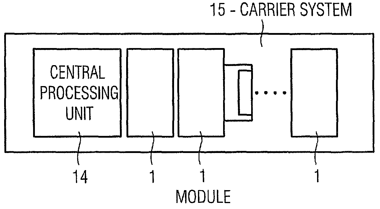
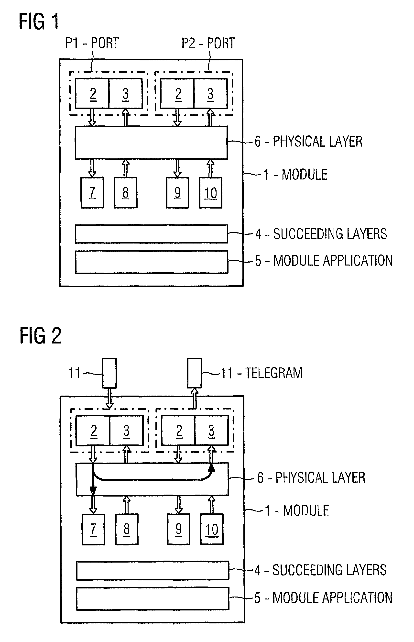
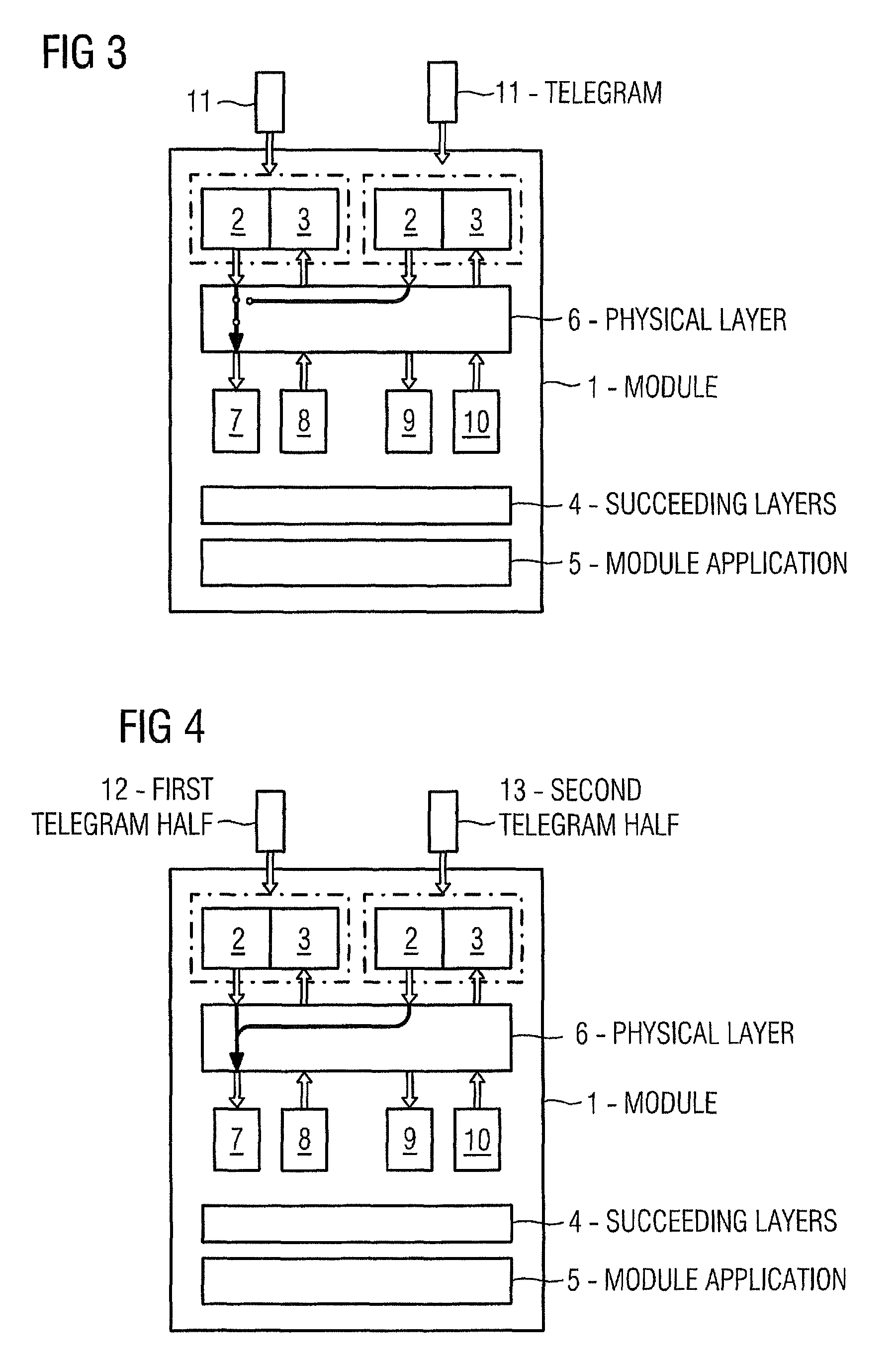
[0030]FIG. 1 shows a schematic representation of an inventive module 1. Said module 1 has two receivers 2 and two transmitters 3 which are combined into two transmitting / receiving devices called ports P1, P2. In this arrangement transmitters 3 and receivers 2 take on the function of a “serializer” and “deserializer” respectively as interfaces to the serial communication system. Telegrams received at the ports P1, P2 are processed further by the physical layer differently depending to the configuration, before they are made available to the succeeding layers 4 and finally the module application 5. In this scheme the succeeding layers 4 consist, according to the OSI model (Open Systems Interconnection Reference Model), of: data link layer, network layer, transport layer, session layer, presentation layer and application layer. In this case the configuration of the physical layer according to the invention has, with one exception, no effect on the succeeding communication layers 4 or, ...


PUM


Abstract

There is described a module for expanding a central module of an automation system, the data transfer between module and central module being accomplished by means of a serial communication system having point-to-point connections in a daisychain or backplane layout and the module having, in a physical layer herefor, at least two transmitters and at least two receivers. There is also described a communication system having at least one module of said kind and a central module. A module for a communication system within an automation system is specified, which module can be flexibly and easily adapted to the respective field of application. There is further described a flexible and scalable communication system for the data transfer between a central module / a CPU and at least one module with the aim of realizing a modular expansion of the central module / CPU. A physical layer can be parameterized in order to adapt it to a predefinable field of application of the module, in particular in terms of speed, availability and / or expandability.

Description

CROSS REFERENCE TO RELATED APPLICATIONS[0001]This application claims priority of European application No. 06015141.2 EP filed Jul. 20, 2006, which is incorporated by reference herein in its entirety.FIELD OF INVENTION[0002]The invention relates to a module for expanding a central module of an automation system, the data transfer between module and central module being accomplished by means of a serial communication system having point-to-point connections in a daisychain or backplane layout and the module having, in a bit transmission layer (“physical layer”) for this purpose, at least two transmitters and at least two receivers.[0003]The invention also relates to a communication system of an automation system having a central module expanded by means of at least one module, the data transfer between module and central module being accomplished serially by means of point-to-point connections in a daisychain or backplane layout.BACKGROUND OF THE INVENTION[0004]A module or communicati...

Claims


Application Information

Patent Timeline
Patent Type & Authority Patents(United States)
IPC IPC(8): H04J3/16
CPCG05B19/0423G06F13/385H04L1/22G05B2219/21027G05B2219/21039
Inventor GROSSER, STEFANMAUL, JURGENTRETTER, ALBERT
Owner SIEMENS AG
Why Eureka
Try Eureka