
Electrical power generation method

a technology of electrical power generation and method, applied in the direction of gaseous engine fuel, indirect carbon-dioxide mitigation, steam use, etc., can solve problems such as thermal inefficiency, and achieve the effect of conserving the amount of material used

Inactive Publication Date: 2010-12-28
PRAXAIR TECH INC
View PDF24 Cites 60 Cited by
  • Summary
  • Abstract
  • Description
  • Claims
  • Application Information

AI Technical Summary

Benefits of technology

This method enhances thermal efficiency and reduces costs by eliminating the need for expensive gas turbines and solvent recovery units, while achieving high-purity carbon dioxide capture for industrial uses.

Problems solved by technology

This thermal inefficiency is due to the fact that the carbon dioxide is removed from the synthesis gas in a solvent system that requires the synthesis gas to be cooled to near ambient temperatures and the energy input that is required to operate the solvent system.

Method used


Image

  • Electrical power generation method
  • Electrical power generation method
  • Electrical power generation method

Examples


Embodiment Construction

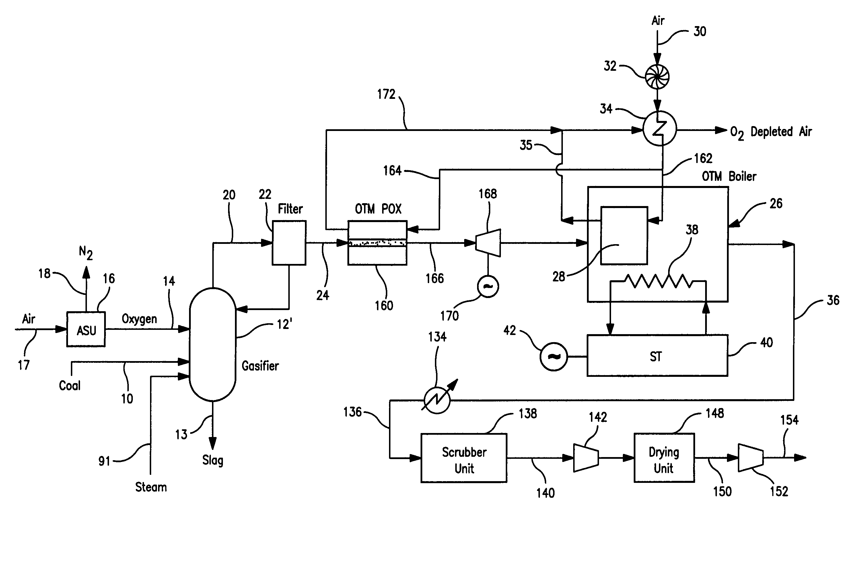
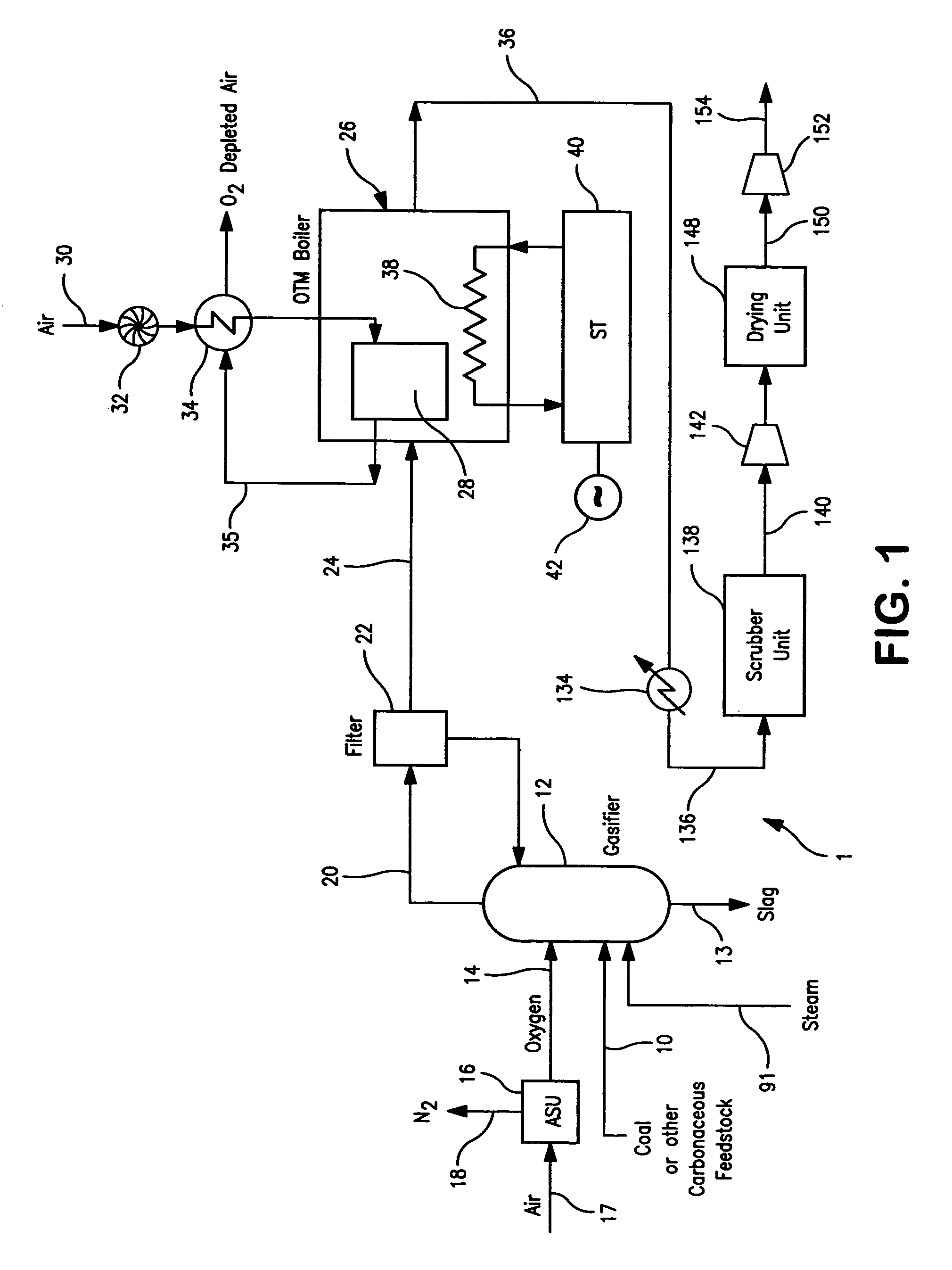
[0029]With reference to FIG. 1, the present invention illustrates an apparatus 1 for carrying out a method in accordance with the present invention in which coal is gasified. This is for exemplary purposes because as indicated above, feed stock to be gasified could be other substances such as coal, asphalt, heavy oil, petroleum coke, biomass or natural gas.

[0030]In accordance with FIG. 1, a prepared coal feed stream 10 is gasified within a gasifier 12 with the addition of a gasifying agent such as an oxygen stream 14. Oxygen stream 14 is created by the cryogenic rectification of air within a cryogenic rectification unit 16. In some gasifiers such as moving bed gasifiers high pressure steam as a steam stream 91, to be discussed, is also injected into the gasifier.

[0031]Cryogenic rectification unit 16 (“ASU”) consists of a compressor to compress an air stream 17 and a purifier to remove the higher boiling contaminants such as carbon dioxide, water and hydrocarbons. The resultant purif...


PUM

PropertyMeasurementUnit
temperatureaaaaaaaaaa
pressureaaaaaaaaaa
pressureaaaaaaaaaa

Abstract

A method of generating electrical power in which a synthesis gas stream generated in a gasifier is combusted in an oxygen transport membrane system of a boiler. The combustion generates heat to raise steam to in turn generate electricity by a generator coupled to a steam turbine. The resultant flue gas can be purified to produce a carbon dioxide product.

Description

FIELD OF THE INVENTION[0001]The present invention relates to a method of generating electrical power in which a synthesis gas stream, produced in a gasifier, is combusted to generate heat that is used to raise steam and that is in turn used in a steam turbine to generate electrical power. More particularly, the present invention relates to such a method in which the synthesis gas stream is combusted in a boiler that employs an oxygen transport membrane to supply oxygen to support the combustion and that has provision for the purification of the resultant flue gases to produce a carbon dioxide-rich stream for further utilization or sequestration.BACKGROUND OF THE INVENTION[0002]Coal-fired power plants are utilized throughout the world to generate electricity. Typically, the coal is either in a pulverized form or within a slurry is combusted to generate heat within a boiler to raise steam. The steam is passed into a steam turbine to generate electrical power.[0003]There has been recen...

Claims


Application Information

Patent Timeline
Patent Type & Authority Patents(United States)
IPC IPC(8): F02C6/18C01B32/50
CPCB01D53/75C01B13/0251C10J3/466F01K23/068C10J3/06C10K1/004C10K1/024C10K3/005B01D53/77B01D2256/22B01D2257/302B01D2257/80B01D2259/40C01B2210/0046C10J2300/093C10J2300/0959C10J2300/0973C10J2300/1606C10J2300/1671C10J2300/1675C10J2300/1678C10J2300/1687C10J2300/1838C10J2300/1876C10J2300/1892F23J2215/20F23J2215/50F23L2900/07005Y02C10/06Y02E20/18Y02E20/34Y02C20/40F01K19/04F01K25/08F01K27/00
Inventor SHAH, MINISH MAHENDRAJAMAL, AQILDRNEVICH, RAYMOND FRANCISVAN HASSEL, BART ANTONIECHRISTIE, GERVASE MAXWELLKOBAYASHIBOOL, III, LAWRENCE E.
Owner PRAXAIR TECH INC
Learn More