Cathode

a cathode and shielding screen technology, applied in the field of cathodes, can solve the problems of poor blocking capability and the ability to achieve blocking capability, and achieve the effects of good blocking capability, high electron emission, and greater lifespan

Active Publication Date: 2011-01-04
SIEMENS HEALTHCARE GMBH
View PDF7 Cites 7 Cited by
  • Summary
  • Abstract
  • Description
  • Claims
  • Application Information

AI Technical Summary

Benefits of technology

[0009]An object of the present invention is to provide a cathode with a high electron emission and a greater lifespan as well as a good blocking capability.
[0012]The disadvantage of a poorer blocking capability, or a blocking capability that can be achieved only with a higher barrier voltage, is remedied by the inventive measure of at least one electrically conductive barrier plate that is galvanically separated from the surface emitter, extending to the surface emitter. The cathode according to the invention thus can also be used for applications in which a fast blocking capability of the electron emission is required. In spite of the fast blocking capability, the cathode according to the invention also exhibits a long lifespan.

Problems solved by technology

The disadvantage of a poorer blocking capability, or a blocking capability that can be achieved only with a higher barrier voltage, is remedied by the inventive measure of at least one electrically conductive barrier plate that is galvanically separated from the surface emitter, extending to the surface emitter.

Method used


Image

  • Cathode
  • Cathode

Examples


Embodiment Construction

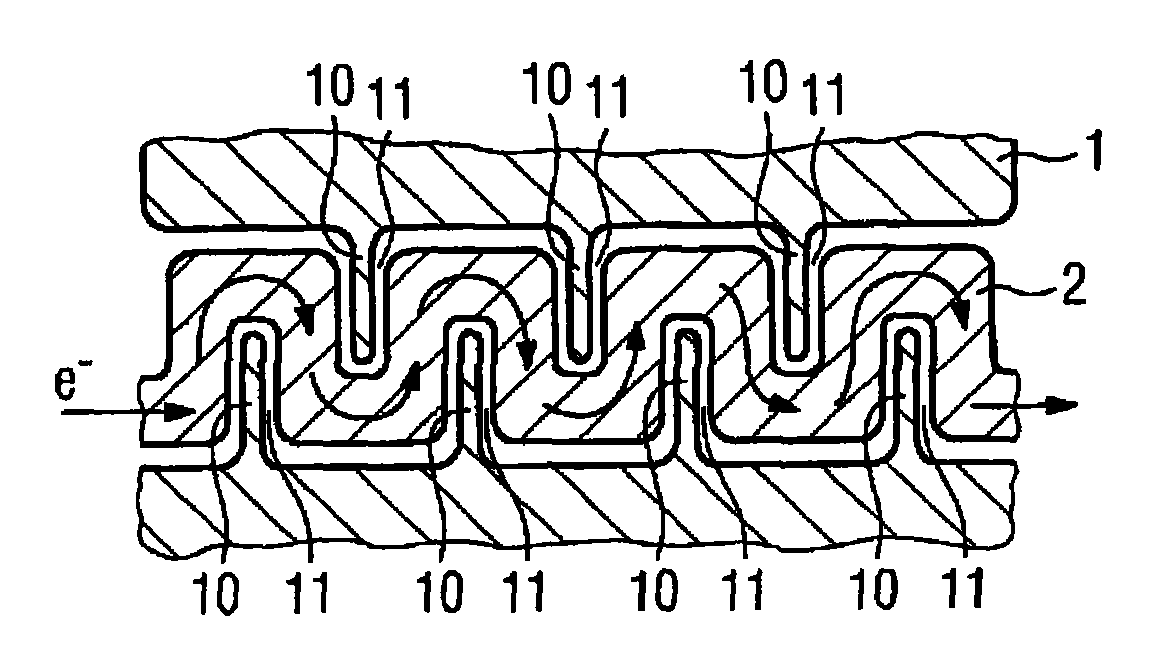
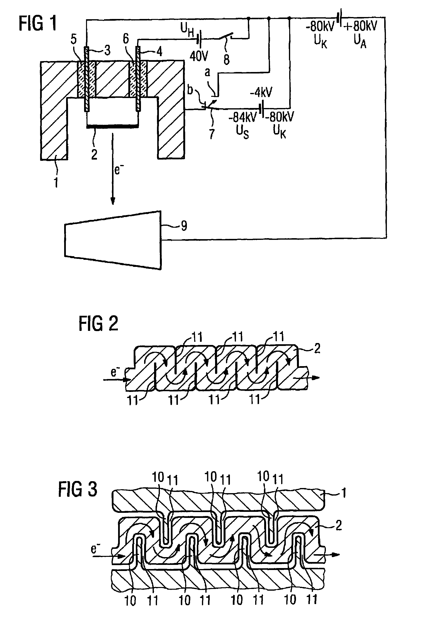
[0021]The cathode shown in FIG. 1 has a cathode head 1 in which is arranged a surface emitter 2.

[0022]The cathode shown in FIG. 1 comprises a cathode head 1 in which is arranged a surface emitter 2.

[0023]The surface emitter 2 is set at an operating voltage UK of −80 kV atop contact pins 3 and 4 that are held insulated in the cathode head 1 via ceramic feedthroughs 5 and 6.

[0024]Furthermore, the cathode head 1 can be selectively switched to the operating voltage UK of −80 kV or to a voltage US of −84 kV via a switching element 7. If the switching element 7 is located in the switch position a, the operating voltage UK of −80 kV is present at the cathode head 1. In the switch position b of the switching element 7, the voltage US of −84 kV is present at the cathode head 1, thus 4 kV more than at the surface emitter 2. A barrier voltage of 4 kV is thus present.

[0025]The contact pin 4 can additionally be switched to a heating voltage UH via a switching element 8.

[0026]If the cathode head ...


PUM


Abstract

A cathode has a cathode head in which is arranged a surface emitter is arranged that emits electrons upon the application of a heating voltage. At least one electrically conductive barrier plate that is galvanically separated from the surface emitter extends up to the surface emitter. This cathode has a longer lifespan, a high electron emission and a good blocking capability.

Description

BACKGROUND OF THE INVENTION[0001]1. Field of the Invention[0002]The invention concerns a cathode.[0003]2. Description of the Prior Art[0004]Cathodes that have a spiral emitter (spiral-wound filament) or surface emitter are used in x-ray tubes, for example. A cathode with a spiral emitter is known from DE 199 55 845 A1, for example. Cathodes that have surface emitters are described in DE 27 27 907 C2 and in DE 199 14 739 C1, for example.[0005]In operation of the x-ray tube, heating voltage is applied to the spiral emitter or to the surface emitter, causing electrons to be emitted that are accelerated in the direction of an anode. X-ray radiation is generated in the surface of the anode upon the electrons striking the anode.[0006]The high temperature of the spiral-wound filament produces a vaporization of the material (tungsten), and a slow thinning of the spiral filament results from this that ultimately leads to a fracture of the spiral filament. This effect is generally known in fi...

Claims


Application Information

Patent Timeline
Patent Type & Authority Patents(United States)
IPC IPC(8): H01J35/06
CPCH01J35/06H01J2235/06H01J35/064
Inventor KUTSCHERA, WOLFGANG
Owner SIEMENS HEALTHCARE GMBH
Why Eureka
Try Eureka