Apparatus for measuring the characteristics of an optical fiber

a technology of optical fibers and optical fibers, applied in the field of optical fiber characteristics apparatuses, can solve the problems of high cost, complicated structure of devices realizing brillouin optical time domain analysis (botda) or bocda, and the inability to accurately measure the center frequency of brillouin scattered light, etc., to achieve high spatial resolution, improve spatial resolution, and facilitate detection

Inactive Publication Date: 2011-01-18
YOKOGAWA ELECTRIC CORP +1
View PDF7 Cites 20 Cited by
  • Summary
  • Abstract
  • Description
  • Claims
  • Application Information

AI Technical Summary

Benefits of technology

[0018]It is another object of the present invention to provide an apparatus for measuring the characteristics of an optical fiber by utilizing Brillouin scattering phenomenon, where a signal light is launched into only one end of the optical fiber, thereby realizing a high spatial resolution.
[0020]It is a still further object of the present invention to provide a method of measuring the characteristics of an optical fiber by utilizing Brillouin scattering phenomenon, where a signal light is launched into only one end of the optical fiber, thereby realizing a high spatial resolution.
[0021]In accordance with one aspect of the present invention, an apparatus for measuring the characteristics of an optical fiber may include, but is not limited to, an optical pulse generator, a detector, a signal processor, and a frequency-varying device. The optical pulse generator generates a series of first and second optical pulses from a coherent light. The first and second optical pulses have a time interval between them. The time interval is equal to or shorter than a life time of an acoustic wave in the optical fiber. The optical pulse generator emits the series of first and second optical pulses toward the optical fiber. The detector couples the coherent light with a Brillouin backscattered light which includes first and second Brillouin backscattered lights belonging to the first and second optical pulses respectively, thereby generating an optical signal. The detector further converts the optical signal into an electrical signal. The signal processor takes the sum of the electrical signal and a delay electrical signal which is delayed from the electrical signal by a delay time corresponding to the time interval, thereby generating an interference signal, the signal processor finding the characteristics of the optical fiber based on the interference signal. The frequency-varying device allows the signal processor to obtain a Brillouin spectrum from the electrical signal.
[0027]In accordance with the present invention, a series of first and second optical pulses is generated from a coherent light, wherein the first and second optical pulses have a time interval between them, which is equal to or shorter than a life time of an acoustic wave in the optical fiber. The coherent light is coupled with a Brillouin backscattered light which includes first and second Brillouin backscattered lights belonging to the first and second optical pulses respectively, thereby generating an optical signal. The optical signal is converted into an electrical signal. There is taken the sum of the electrical signal and a delay electrical signal which is delayed from the electrical signal by a delay time corresponding to the time interval, thereby generating an interference signal. The characteristics of the optical fiber are found based on the interference signal. A Brillouin spectrum included the interference signal is steeper than first and second Brillouin spectrums of the first and second Brillouin backscattered lights belonging to the first and second optical pulses respectively. Measuring the characteristics of the optical fiber based on the interference signal makes it easy to detect the Brillouin frequency shift, thereby improving the spatial resolution.

Problems solved by technology

Extensively narrowing the pulse width beyond the narrower limit makes it difficult to accurately measure the center frequency of the Brillouin scattered light.
These documents fail to propose improvement of the spatial resolution of the Brillouin optical time domain reflectometry (BOTDR).
The device realizing the Brillouin optical time domain analysis (BOTDA) or the Brillouin optical correlation domain analysis (BOCDA) is likely to be complicated in structure and highly expensive.

Method used


Image

  • Apparatus for measuring the characteristics of an optical fiber
  • Apparatus for measuring the characteristics of an optical fiber
  • Apparatus for measuring the characteristics of an optical fiber

Examples


first embodiment

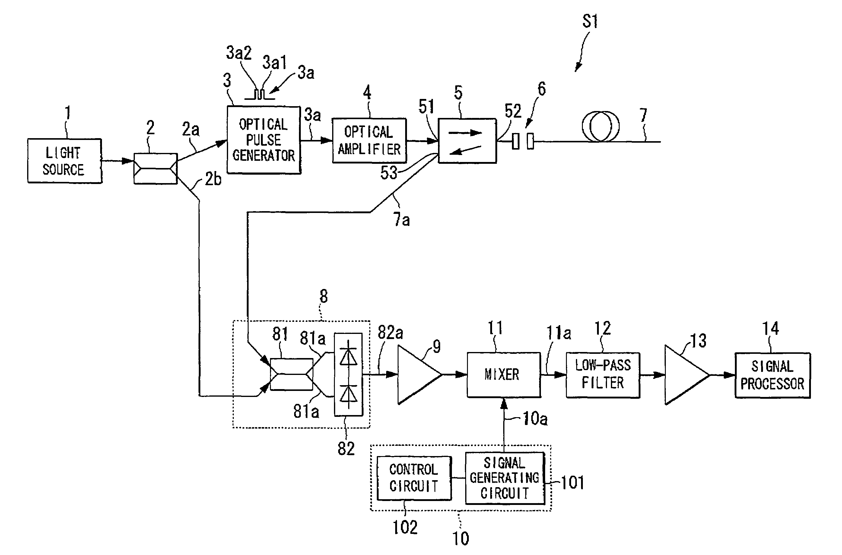
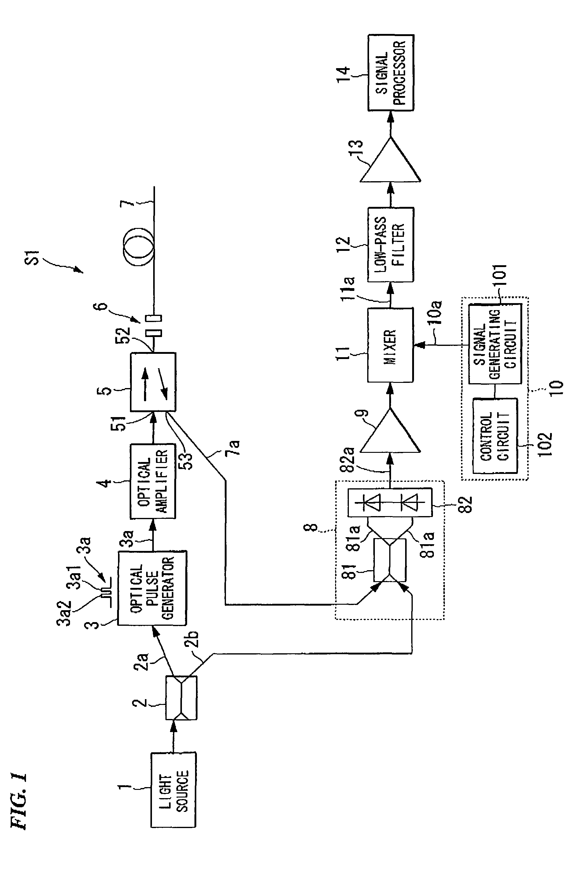
[0043]FIG. 1 is a block diagram illustrating a configuration of an apparatus S1 for measuring the characteristics of an optical fiber in accordance with this first embodiment of the present invention. The apparatus S1 for measuring the characteristics of an optical fiber may include a light source 1, a branch coupler 2, an optical pulse generator 3, an optical amplifier 4, an optical directional coupler 5, an optical connector 6, an optical fiber 7, a balanced light receiving circuit 8, a first amplifier 9, a signal generator 10, a mixer 11, a low-pass filter 12, a second amplifier 13, and a signal processing unit 14. The optical fiber 7 is subjected to measurement by the apparatus S1.

[0044]The light source 1 is configured to emit a coherent light 1a having a narrow line-width and a frequency f0. The light source 1 can be realized by a 1.55 μm-band multiple quantum well distributed feedback (MQW-DFB) semiconductor laser.

[0045]The branch coupler 2 can be configured to divide the cohe...

second embodiment

[0112]A second embodiment of the present invention will be described. The second embodiment provides an apparatus S2 for measuring the characteristics of an optical fiber. The apparatus S2 is different from the apparatus S1 described above. The following descriptions will focus on the difference of the apparatus S2 from the apparatus S1 to avoid duplicate descriptions thereof.

[0113]FIG. 10 is a block diagram illustrating a configuration of an apparatus for measuring the characteristics of an optical fiber in accordance with the second embodiment of the present invention. The apparatus S2 for measuring the characteristics of an optical fiber may include a light source 1, a branch coupler 2, an optical pulse generator 3, an optical amplifier 4, an optical directional coupler 5, an optical connector 6, an optical fiber 7, a balanced light receiving circuit 8, a first amplifier 9, a signal generator 10, a mixer 11, a low-pass filter 12, a second amplifier 13, a signal processing unit 14...

third embodiment

[0120]A third embodiment of the present invention will be described. The third embodiment provides an apparatus S3 for measuring the characteristics of an optical fiber. The apparatus S3 is different from the apparatus S1 described above. The following descriptions will focus on the difference of the apparatus S3 from the apparatus S1 to avoid duplicate descriptions thereof. The apparatus S3 for measuring the characteristics of an optical fiber may include a light source 1, a branch coupler 2, an optical pulse generator 3, an optical amplifier 4, an optical directional coupler 5, an optical connector 6, an optical fiber 7, a balanced light receiving circuit 8, a first amplifier 9, a signal generator 10, a mixer 11, a low-pass filter 12, a second amplifier 13, a signal processing unit 14, and an ASE-light removing optical switch 30.

[0121]The ASE-light removing optical switch 30 is disposed between the optical amplifier 4 and the optical directional couplet 5. The ASE-light removing o...


PUM


Abstract

An apparatus for measuring the characteristics of an optical fiber is provided. An optical pulse generator generates, from a coherent light, first and second optical pulses having a time interval which is equal to or shorter tan a life time of an acoustic wave in the optical fiber. A detector couples the coherent light with a Brillouin backscattered light which includes first and second Brillouin backscattered lights belonging to the first and second optical pulses respectively, thereby generating an optical signal. The detector further converts the optical signal into an electrical signal. A signal processor takes the sum of the electrical signal and a delay electrical signal which is delayed from the electrical signal by a delay time corresponding to the time interval, thereby generating an interference signal, and finds the characteristics of the optical fiber based on the interference signal.

Description

BACKGROUND OF THE INVENTION[0001]1. Field of the Invention[0002]The present invention generally relates to an apparatus for measuring the characteristics of an optical fiber. More specifically, the present invention relates to an apparatus for measuring the characteristics of an optical fiber, wherein the apparatus is configured to launch an optical pulse generated from a coherent light into an optical fiber, mixing the coherent light and a Brillouin backscattered light from the optical fiber to obtain a mixed light signal, converting the mixed light signal into an electric signal, and finding the characteristics of an optical fiber based on the electric signal.[0003]Priority is claimed on Japanese Patent Application No. 2006-336200, filed Dec. 13, 2006, the content of which is incorporated herein by reference.[0004]2. Description of the Related Art[0005]All patents, patent applications, patent publications, scientific articles, and the like, which will hereinafter be cited or ident...

Claims


Application Information

Patent Timeline
Patent Type & Authority Patents(United States)
IPC IPC(8): H04B10/08G01B11/16G01D5/26G01D5/353G01M11/02
CPCG01M11/319
Inventor KOYAMADA, YAHEI
Owner YOKOGAWA ELECTRIC CORP
Why Eureka
Try Eureka