Masking system for the masking of a crank chamber of an internal combustion engine

Inactive Publication Date: 2011-01-25
SULZER METRO AG
View PDF9 Cites 7 Cited by
  • Summary
  • Abstract
  • Description
  • Claims
  • Application Information

AI Technical Summary

Benefits of technology

[0011]It is therefore an object of the present invention to provide an apparatus with which the problems known from the prior art, in particular the thermal problems and the problems with the contamination by metal vapors in the thermal coating of cylinder bores, are avoided, with a high degree of automation simultaneously being achievable in a simple and cost-effective manner.

Problems solved by technology

In such V engines, the risk exists on thermal coating that, during a surface treatment of the cylinder running surfaces, e.g. on the activation, cleaning or another pre-treatment of the cylinder running surfaces, surfaces of the crank chamber of the engine block or cylinder running surfaces of adjacent cylinder bores can also be affected in an uncontrolled manner.
Corresponding problems also occur above all on the thermal coating of the cylinder wall of a cylinder of the internal combustion engine.
Due to the deposition of the metal vapors at the relatively cold walls on the cylinder wall of the cylinder, e.g. of the second cylinder row, this cylinder wall in the second cylinder row is contaminated by the metal vapors, which inter alia has a negative effect on the adhesion of a coating likewise still to be applied to this cylinder later.
In addition, a contamination by unmelted particles and by overspray is to be feared and also the inner surfaces of the crankcase can be contaminated in a disadvantageous manner or also be affected.
A further problem is the heating of the engine block by the thermal coating process.
Since the difference in the thermal coefficient of expansion between the thermal spray coating and the substrate can be relatively high, a temperature of the substrate of more than 120° C., with this substantially having to be understood as a type of mean temperature of the engine block, has a negative effect on the internal stress level of the layers, and above 150° C. there is even the risk that the component made from a light metal alloy, that is, the engine block, suffers deformation of the material and thus becomes unusable.
This problem becomes particularly clear when one looks at the thermal coefficients of expansion of typical materials used: typical coefficients of expansion of thermal spray coatings from alloys on an iron base lie e.g. at approx.
Apparatuses are thus known in which cylinder bores which are not coated are sealed with a type of inflatable balloon, which can, however, lead to heat accumulation and aggravate the above-mentioned problems with the thermal coefficients of expansion even more.
The thermal problems are also ultimately not completely solved here and, which is at least just as important, the use of all known systems can only be automated with great difficulty, if at all, in particular in the case of engines in the V design, so that the coating process ultimately becomes very expensive because a lot of manual work is required in the coating of a large number of engine blocks.

Method used


Image

  • Masking system for the masking of a crank chamber of an internal combustion engine
  • Masking system for the masking of a crank chamber of an internal combustion engine
  • Masking system for the masking of a crank chamber of an internal combustion engine

Examples


Embodiment Construction

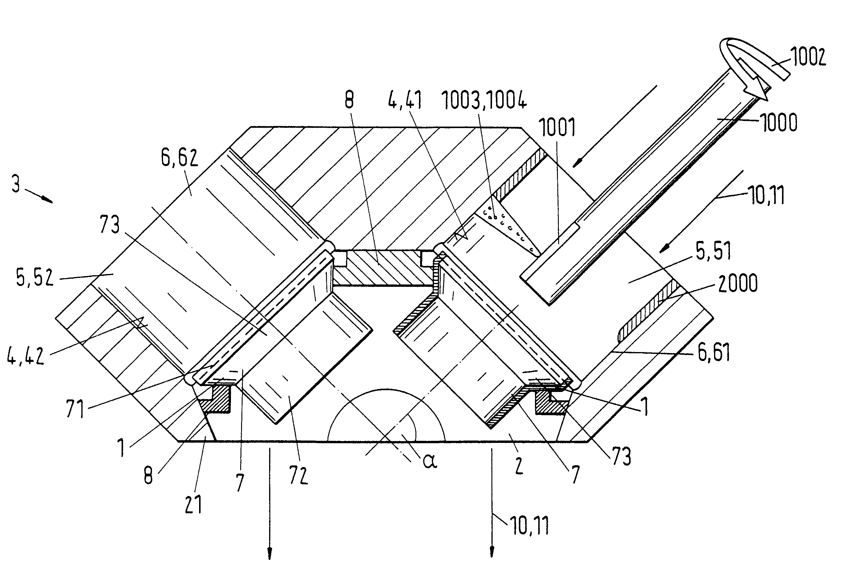
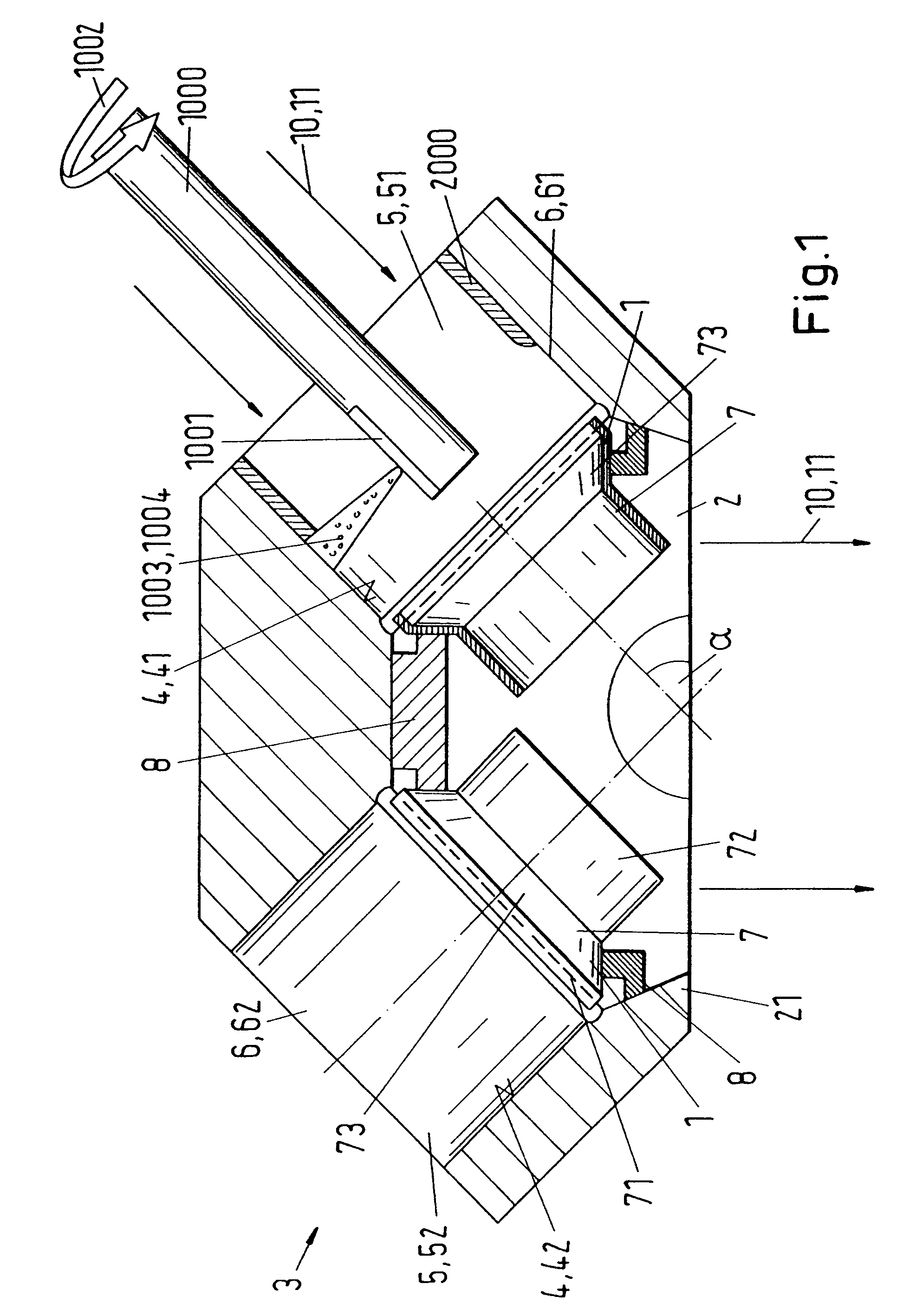
[0068]FIG. 1 and FIG. 3 show, in an illustration in section, two simple embodiment variants of a masking system in accordance with the invention during the coating of a cylinder bore of an engine in a V design at which the function of a masking system in accordance with the invention is schematically explained which is designated in total in the following by the reference numeral 1.

[0069]In this connection, the masking system of FIG. 3 additionally includes a masking element 9 for the protection and for the better cooling of a cylinder running surface 4, 42 not to be coated.

[0070]In FIG. 1 and FIG. 3, a section through an engine block of an engine in the V design is shown whose two cylinder rows are arranged parallel to one another at an angle of inclination α in a known manner.

[0071]A first cylinder 6, 61, the right-hand cylinder in accordance with the representation, is just being coated using a rotating plasma spray gun 1000 known per se. The plasma spray gun 1000 rotates around ...


PUM

PropertyMeasurementUnit
Pressureaaaaaaaaaa
Flow rateaaaaaaaaaa

Abstract

The invention relates to a masking system (1) for the masking of a crank chamber (2) of an internal combustion engine (3) during a surface treatment of a cylinder running surface (4, 41, 42) of a cylinder bore (5, 51, 52) of a cylinder (6, 61, 62) of the internal combustion engine (3). The masking system (1) includes a hollow masking body (7) with a connector segment (71) for the connection of the hollow masking body (7) to the cylinder bore (5, 51, 52) as well as a screen segment (72). In accordance with the invention, the hollow masking body (7) is configured such that the connector segment (71) of the hollow masking body (7) can be positioned on the cylinder bore (51) of the first cylinder (6, 61) at the crank chamber side during the surface treatment of a first cylinder (6, 61) of the internal combustion engine (3). The invention further relates to the use of a masking system (1) in accordance with the invention.

Description

CROSS-REFERENCES TO RELATED APPLICATIONS[0001]This application claims the priority of European patent application No. 06117756.4, filed Jul. 24, 2006, and European patent application No. 07405133.5, filed May 4, 2007, the disclosures of both of which are incorporated herein by reference.BACKGROUND OF THE INVENTION[0002]The invention relates to a masking system for the masking of a crank chamber of an internal combustion machine during a surface treatment of a cylinder running surface as well as to the use of a masking system in accordance with the present invention.[0003]The thermal coating of cylinder running surfaces of internal combustion engines by different thermal spray processes is state of the art today and is in particular widely used on engines for motor vehicles of all types, but not just here. Usually, the corresponding cylinder running surfaces are activated before the thermal coating by different processes, e.g. by corundum blasting, hard cast blasting, high-pressure w...

Claims


Application Information

Patent Timeline
IPC IPC(8): B05C11/11B05B12/18B05B12/20B05B12/26
CPCB05B15/045B05B15/0462B05B15/0431B05B7/20B05B7/22B05B13/0636B05B12/18B05B12/20B05B12/26C23C4/04C23C4/12F02F1/00F16J10/04
Inventor BOHNHEIO, CHRISTIANBARBEZAT, GERARD
Owner SULZER METRO AG
Why Eureka
Try Eureka