Process for coating a substrate

a substrate and coating technology, applied in the field of coating a substrate, can solve the problems of inhomogeneous coating thickness and cracks, and difficult to produce porous coatings, and achieve the effect of being convenient to use and convenient to us

Active Publication Date: 2011-02-22
IOOS LLC
View PDF11 Cites 2 Cited by
  • Summary
  • Abstract
  • Description
  • Claims
  • Application Information

AI Technical Summary

Benefits of technology

[0010]The main object of the invention is to provide a cost-effective and flexible method to form a polymer coating on a substrate having desired surface properties in terms of surface roughness and surface area.
[0012]It is still another object to minimize coating compaction and to increase porosity and surface area of the coating.

Problems solved by technology

The comparatively high coating compaction of the produced coating may however result in an inhomogeneous coating thickness and cracks.
In addition, it may be difficult to produce porous coatings, which can be used in medical implants as reservoirs for the retention of therapeutic agents and may be desirable to enhance tissue ingrowth and tissue healing.
Also, conventional coating methods, such as described in U.S. Pat. No. 6,143,370, may not allow the coating of a stent so that the morphology of the coating layer can be changed instantaneously, which may be desirable to accommodate the need for different elution profiles as may be required by the medical application.

Method used


Image

  • Process for coating a substrate
  • Process for coating a substrate
  • Process for coating a substrate

Examples


example i

[0076]Several stents were coated according to the process of the present invention. A poly(vinylidene fluoride) PVDF HFP copolymer with a monomer composition of 80% vinylidene fluoride and 10% hexaflouropropylene (Solvay Advanced Polymers, Houston, Tex., USA) was used to coat the stents. The coating solution was prepared by dissolving the polymers in acetone, at five weight percent. Both the inside and the outside surfaces of the stents were coated. Care was taken so that the stents were coated at the same operating conditions. The swirl intensity was precisely adjusted to examine its influence on the resulting surface properties. Several scanning electron microscope (SEM) images were taken to visualize the surface morphology at different swirl intensities.

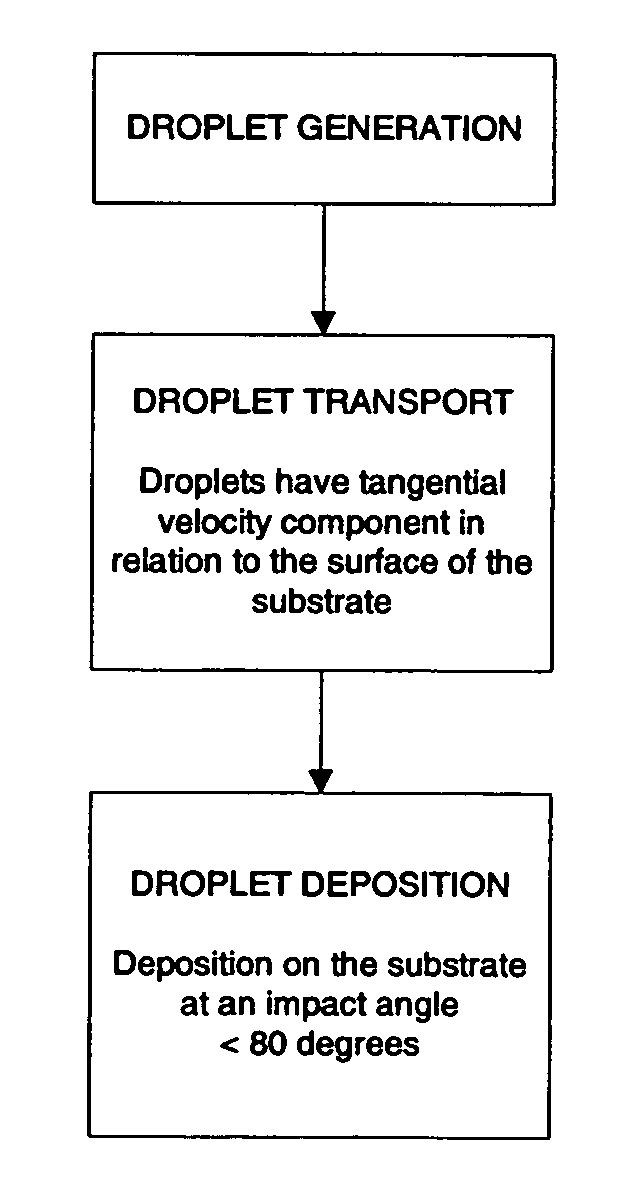
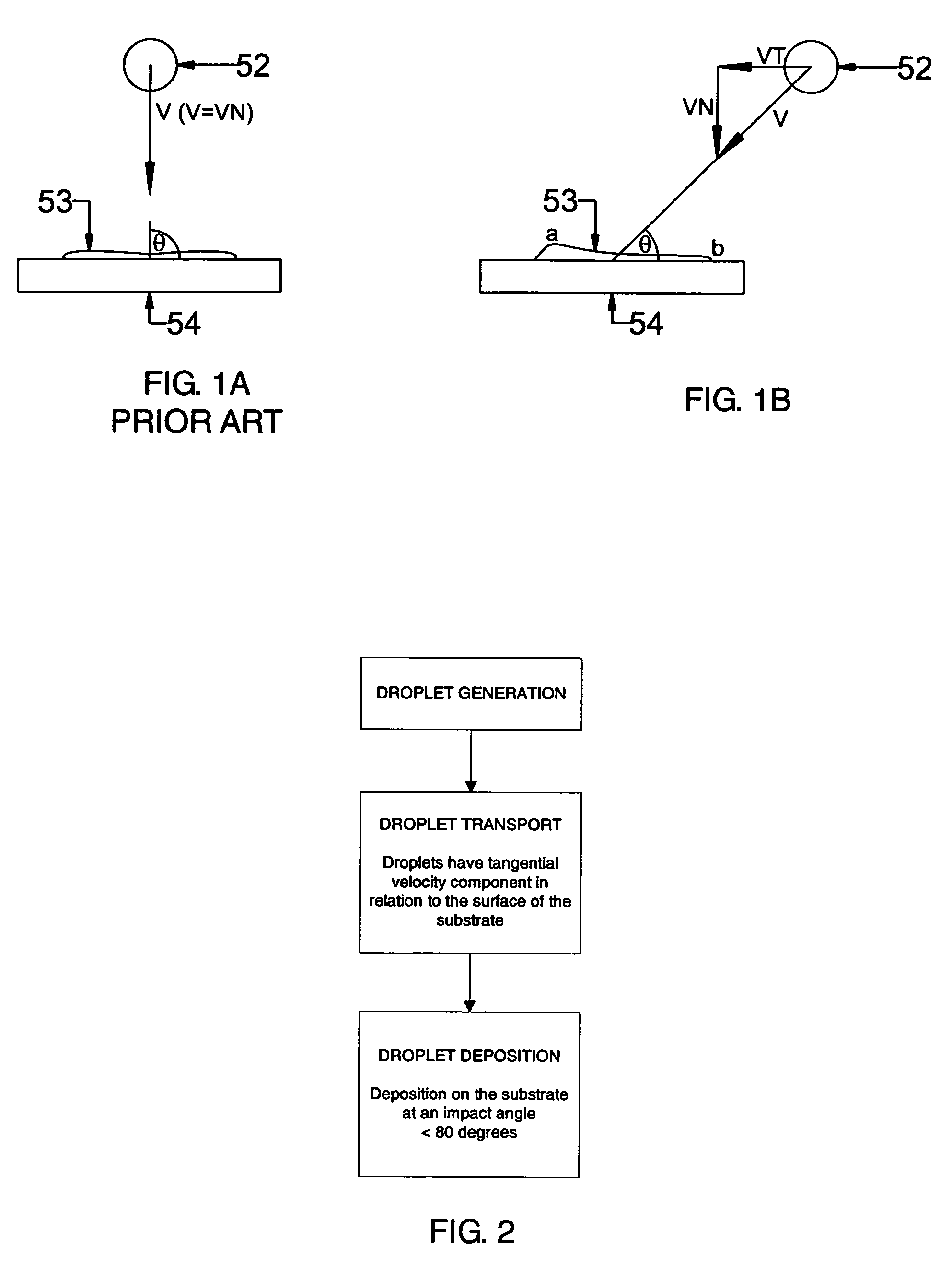
[0077]Stent #1 was coated at a swirl intensity of 0. The coating was applied according to the schematic representation of FIG. 1A so that the majority of the droplet hit the surface at an impact angle of about 90 degrees. FIG. 11A...

example ii

[0081]Several stents were coated according to the process of the present invention using the poly(tetrafluoroethylene) dispersion PTFE 307A (DuPont, Wilmington, Del., USA). The dispersion contains approximately 60% (by total weight) of 0.05 to 0.5 μm c resin droplets suspended in water and approximately 6% (by weight of PTFE) of a nonionic wetting agent and stabilizer. Both the inside and the outside surfaces of the stents were coated. The stents were coated at a swirl intensity of 0.3 according to the schematic representation of FIG. 1B. FIGS. 12A-C are scanning electron microscope (SEM) images of the coating morphology produced on a stent according to the process of the present invention at various magnifications.

[0082]Referring to FIG. 12A, a stent having a homogeneous coating with a comparatively large surface area and roughness is shown. Accumulation of excess material on the surface of the stent was not observed and the coating looked uniform.

[0083]To better visualize the morp...


PUM

PropertyMeasurementUnit
impact angleaaaaaaaaaa
velocityaaaaaaaaaa
impact angleaaaaaaaaaa

Abstract

A method to coat a substrate for the formation of coatings having a desired surface morphology is provided, wherein the roughness and the total surface area of the coating can be varied during the coating process. The method of the present invention comprises the steps of generating droplets from a coating composition, transporting the droplets to the substrate and depositing a majority of the droplets on the substrate.

Description

CROSS-REFERENCE TO RELATED APPLICATIONS[0001]Not ApplicableFEDERALLY SPONSORED RESEARCH[0002]Not ApplicableSEQUENCE LISTING OR PROGRAM[0003]Not ApplicableBACKGROUND OF THE INVENTION[0004]The present invention relates to an apparatus and method for applying a coating to at least a portion of a substrate having desired surface properties. In particular, the invention relates to a method for producing polymer coatings with various morphologies on medical implants, such as stents.[0005]Coatings are often applied to medical implants, such as pacemakers, vascular grafts, catheters, stents, heart valves, tissues or sensors to have desired effects and increase their effectiveness. These coatings may deliver a therapeutic agent to the lumen that reduces smooth muscle tissue proliferation or restenosis and may comprise a polymer carrier. Furthermore, implants may be coated to improve surface properties such as lubriciousness, to achieve enhanced biocompatibility and to control the timing and ...

Claims


Application Information

Patent Timeline
Patent Type & Authority Patents(United States)
IPC IPC(8): B05D1/02B05D5/02B05B1/00
CPCA61L31/10A61L31/16A61L2300/606A61L2420/02
Inventor SCHEER, INGO WERNER
Owner IOOS LLC
Why Eureka
Try Eureka