
Method of improving hydrocarbon production from a gravel packed oil and gas well

a technology of hydrocarbon production and gravel, which is applied in the direction of fluid removal, borehole/well accessories, chemistry apparatus and processes, etc., can solve the problems of affecting the permeability of the formation, and affecting the production rate, so as to increase the conductivity of the gravel pack and the resulting productivity of the oil reservoir

Inactive Publication Date: 2011-03-01
CSI TECH LLC A TEXAS LLC
View PDF4 Cites 20 Cited by
  • Summary
  • Abstract
  • Description
  • Claims
  • Application Information

AI Technical Summary

Benefits of technology

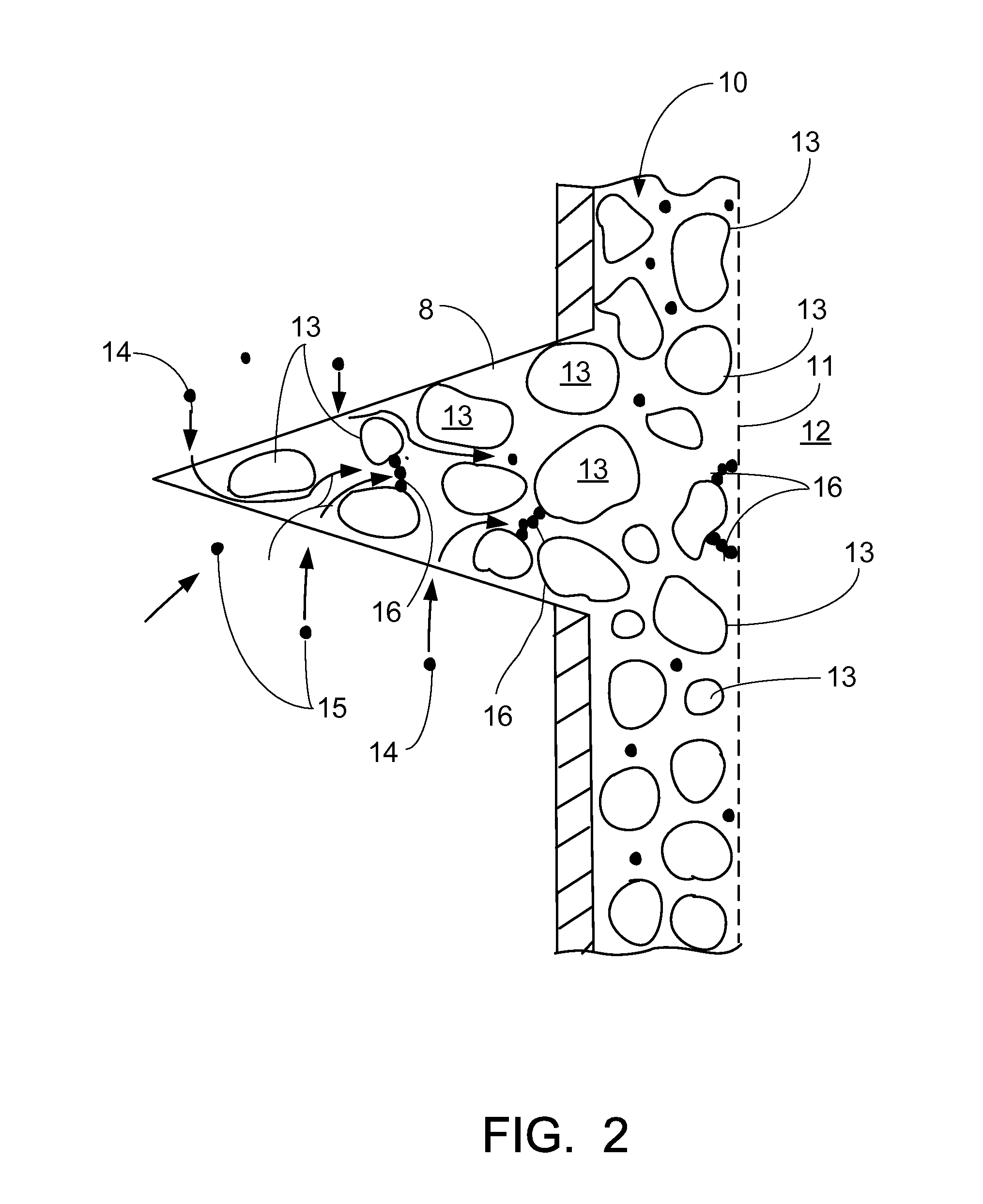
[0011]The present invention provides a method of removing fine particulate matter (fines) deposited into a gravel pack. Application of the invention results in removal of fines from the pack thereby increasing the conductivity of the gravel pack and the resulting productivity of the oil reservoir.
[0014]A water-based flush follows the chemical flush. The function of the water based flush is to displace any fine particulate matter or fines not dissolved by the chemical wash and to displace reaction products from the chemical stage sufficiently far into the well bore so that any resulting precipitation will not damage the near well bore area. Injection of aqueous flush is initially at same rate as chemical flush. After half the volume of flush is placed, injection rate is increased to increase mechanical energy applied to the remaining fines.
[0017]The chemical portion employs an organic solvent, an HCL or organic acid preflush, and an HF or combination of HCL:HF acid flush to dissolve any organics, silt and clays deposited in the pack. This chemical portion of the fluid train is then pushed far back into the formation by an overflush. The overflush can be acid, treated water, or a combination of the two and is designed to fulfill two purposes. First, the overflush sweeps the chemical flush laden with reaction products far out into the surrounding formation. Volumetric design includes sufficient overflush to sweep the chemical flush a distance away from the well bore. This physical removal of reactive fluids prevents any secondary precipitation of products from the fluids to leave damaging solids in the gravel pack or near well bore. The volume of overflush is designed to sweep the chemical flush preferably about three feet (3′) or more from the well bore. Thus, if any precipitation would occur with time, the damage to permeability so far away from the well bore would be minimal. A second purpose of the overflush is to sweep from the gravel pack any fines not dissolved or removed from the pack by the chemical flush. The method of the present invention can thus include the step of increasing displacement rate of the overflush several times throughout the injection to take advantage of penetration of fluids into less permeable formation driven by increased injection pressure derived from increased overflush flow rate.
[0018]A methanol-water mixture is injected into the pack and left until the well is returned to production. This mixture is left in the pack to eliminate potential for any adverse reaction with the overflush and to improve wettability of sand to hydrocarbon, to reduce surface tension and to further dissolve any blocking material.
[0021]The treatment of the present invention alleviates any need for extensive design. Any gravel pack with production decline over time is a candidate. Users should be aware of decline rates versus predicted production decline resulting from reservoir depletion. Any decreased production in excess of that predicted by reservoir depletion curves is assumed to be a result of increased damage to the gravel pack. Treatment design is based on height of gravel pack screen in place. The height of screen is multiplied by the specified volume per foot of each fluid to establish injection volumes.
[0031]One potential application difficulty might arise if one portion of the perforated interval takes injected fluid much more easily than the rest of the perforations. If that is the case, the gravel pack may not be completely contacted and treated by the injected fluid train. Moving the coiled tubing end up and down the length of the screen interval during the injection procedure alleviates the possibility of injecting through the pack at only one point. This practice would maximize the probability of complete pack treatment.

Problems solved by technology

Formations that exhibit a tendency to release formation particles during hydrocarbon production (commonly called “sanding” or “fines migration”) create problems as these particles are released into the hydrocarbon stream.
Particles can bridge in formation flow channels and impede production rate.
Such particles can settle into the bottom of a well bore and impede production.
This gravel pack type of completion method always damages the permeability of the formation compared to native permeability of the reservoir rock.
Additionally, as fines migrate into the well and are trapped by the gravel pack, permeability is further reduced resulting in reduced production rates.

Method used


Image

  • Method of improving hydrocarbon production from a gravel packed oil and gas well
  • Method of improving hydrocarbon production from a gravel packed oil and gas well
  • Method of improving hydrocarbon production from a gravel packed oil and gas well

Examples


Embodiment Construction

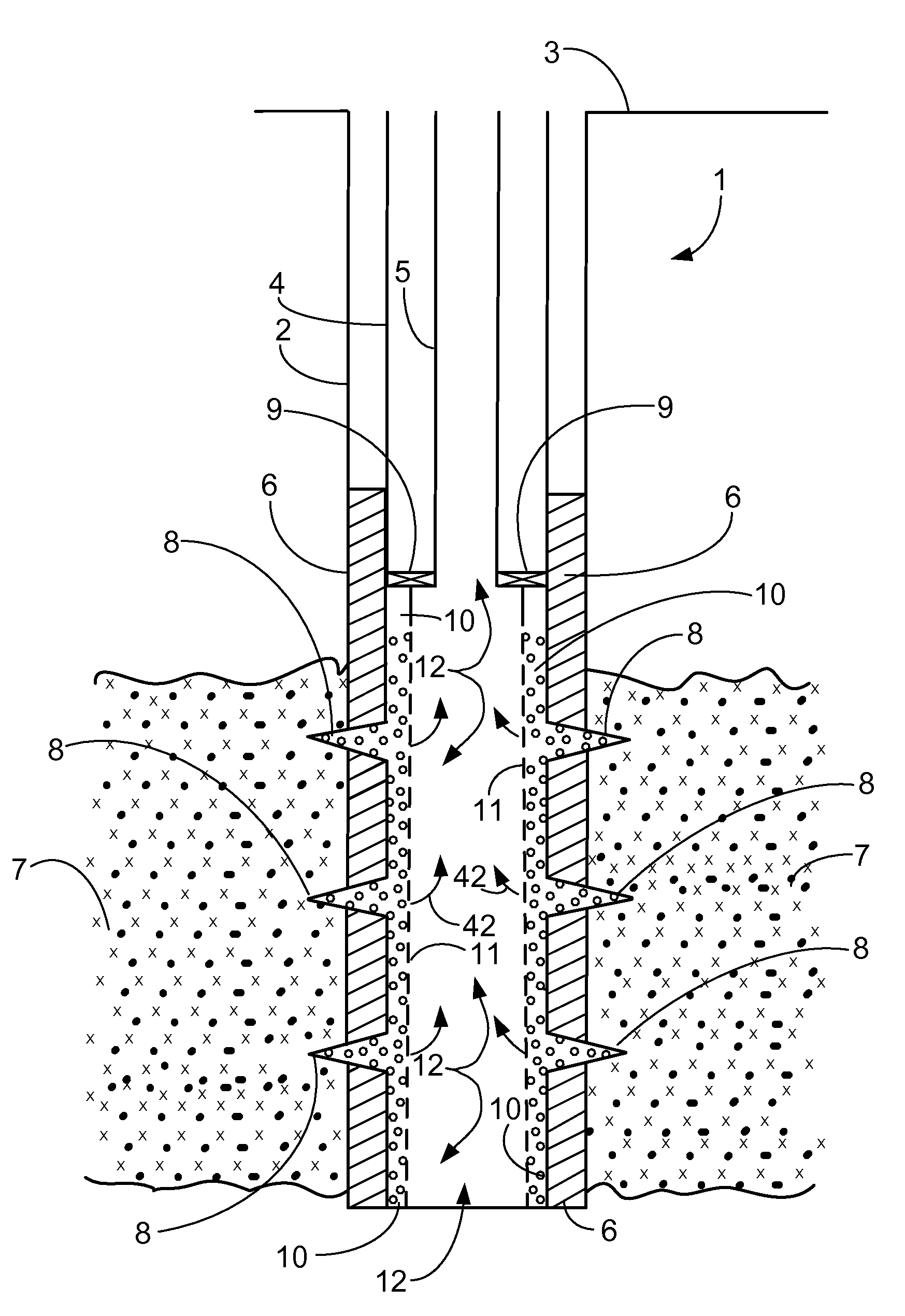
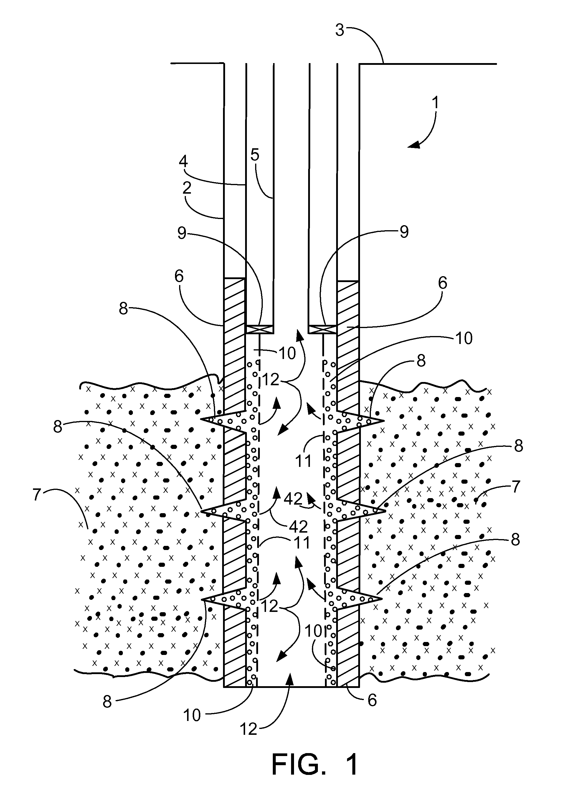
[0053]FIG. 1 shows a typical well that has been completed using a gravel pack. In FIG. 1, the oil and gas well 1 provides a borehole 2 that extends downwardly from the earth's surface 3. Casing 4 can be used to line the well borehole 2 as shown in FIG. 1. A production tubing 5 extends internally of the casing 4 in a manner that is known in the art. The production tubing 5 extends downwardly to a position next to a producing formation 7. A cemented annulus 6 can be formed in between producing formation 7 and casing 4. Production packer 9 is placed in between production tubing 5 and casing 4 above the producing formation 7.

[0054]A plurality of perforations 8 extend through cemented annulus 6 and communicate with the producing formation 7. Gravel pack 10 is placed in between screen 11 and cemented annulus 6. Oil and gas that is produced from well 1 flows from producing formation 7 through perforations 8, then through gravel pack 10 and screen 11 to well bore 12. Arrows 42 in FIG. 1 sch...


PUM


Abstract

This invention relates to enhancing hydrocarbon production from a subterranean formation via a well completed with a gravel pack. Gravel packs suffer plugging and damage over time from produced particles and other plugging materials brought into the pack as production continues. This invention relates to a chemical treatment for the gravel pack designed to remove damaging particulate matter from the pack via dissolution or displacement. Damaging material is forced sufficiently far into the producing reservoir to prevent its remigration back into the pack.

Description

CROSS-REFERENCE TO RELATED APPLICATIONS[0001]Not applicableSTATEMENT REGARDING FEDERALLY SPONSORED RESEARCH OR DEVELOPMENT[0002]Not applicableREFERENCE TO A “MICROFICHE APPENDIX”[0003]Not applicableBACKGROUND OF THE INVENTION[0004]1. Field of the Invention[0005]The present invention relates to a method of improving hydrocarbon production from a reservoir that was completed with a gravel pack, wherein fine particles that clog the gravel pack are removed from the gravel pack so that hydrocarbon production is increased.[0006]2. General Background of the Invention[0007]Formations that exhibit a tendency to release formation particles during hydrocarbon production (commonly called “sanding” or “fines migration”) create problems as these particles are released into the hydrocarbon stream. Particles can bridge in formation flow channels and impede production rate. Particles carried into a well bore with produced hydrocarbon can also erode well structure such as tubulars and well heads. Suc...

Claims


Application Information

Patent Timeline
IPC IPC(8): E21B21/00E21B37/08
CPCC09K8/74E21B37/08
Inventor WATTERS, LARRYWATTERS, JEFFAMMACHATHRAM, MAHADEV
Owner CSI TECH LLC A TEXAS LLC
Learn More