Method and apparatus for the milling cutting of materials

a cutting method and material technology, applied in cutting machines, slitting machines, surface mining, etc., can solve the problems of high releasing force of each individual cutting tool, high wear even of cutting tools provided with hard metal tips, and noise pollution that can present considerable problems

Active Publication Date: 2011-03-01
CATERPILLAR INC
View PDF14 Cites 13 Cited by
  • Summary
  • Abstract
  • Description
  • Claims
  • Application Information

AI Technical Summary

Benefits of technology

[0006]The object of the invention is to provide an apparatus which is capable of economically removing even rock or other materials having high strengths, with a high removal performance and with a large removal surface. The apparatus is to ensure high operating reliability, is to be capable of being used in the most diverse possible fields of use and is to avoid the disadvantages of the known apparatus which have been indicated.
[0010]In order to achieve a favorable release behavior in the case of a common rotary drive for the tool drum and for the tool shafts, the gear preferably has a step-up ratio of between about 3:1 and 9:1, in particular of about 6:1 and 8:1, between the drive shaft and the tool shafts. Where particularly hard cutting tools, such as, for example, diamond tools or ceramics, are concerned, the step-up ratio may even amount, for example, to 12:1 and higher. So that 
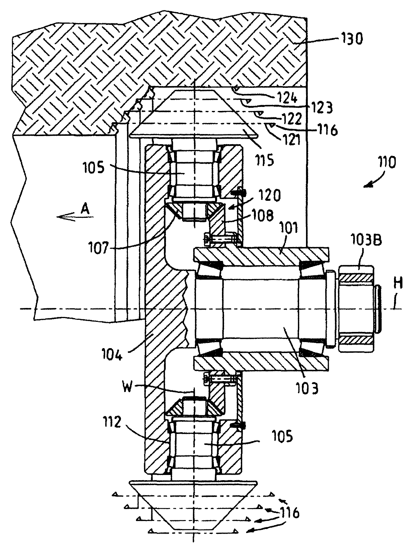
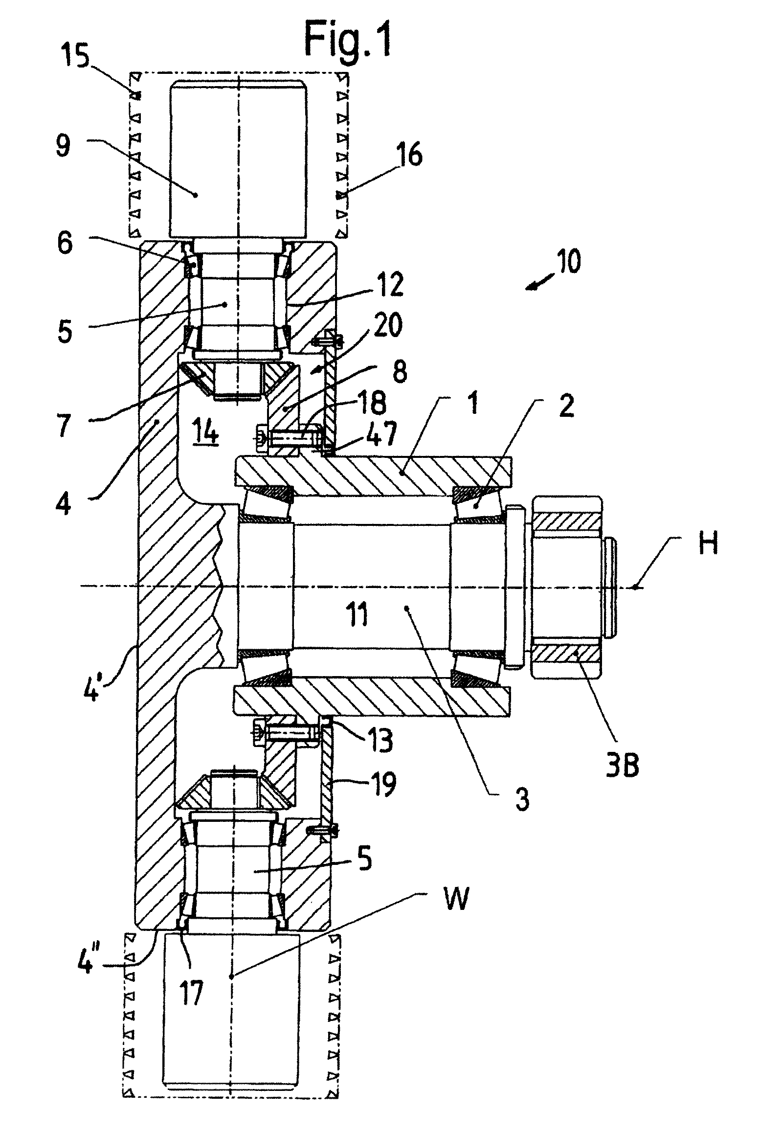
high pressure forces can easily be absorbed, according to an advantageous refinement the tool drum may be supported on both sides of the tool shafts on a drum carrier, a journal or a bearing for holding the tool drum on two sides being formed preferably on that side of the tool drum which lies opposite the drive device. In the case of smaller tool drums or softer materials to be broken down, however, it can be sufficient even to hold the tool drum on one side.
[0013]According to a further advantageous alternative refinement, the tool drum may be connected fixedly in terms of rotation to the power take-off side of a first hub gear and the driving gearwheel may be connected fixedly in terms of rotation to the power take-off side of a second hub gear, the two hub gears being arranged in a central receptacle. A refinement of this type has a particularly compact build and can therefore easily be moved along a large working face by means of pivoting arms or the like. The hub gears may, in particular, be designed as push-in gears with gear stages preferably arranged, encapsulated, in gear cases, the fastening flanges of the two hub gears being fastenable or fastened to the drum carrier. The drive of the hub gears could also take place, in particular, via toothed belts.
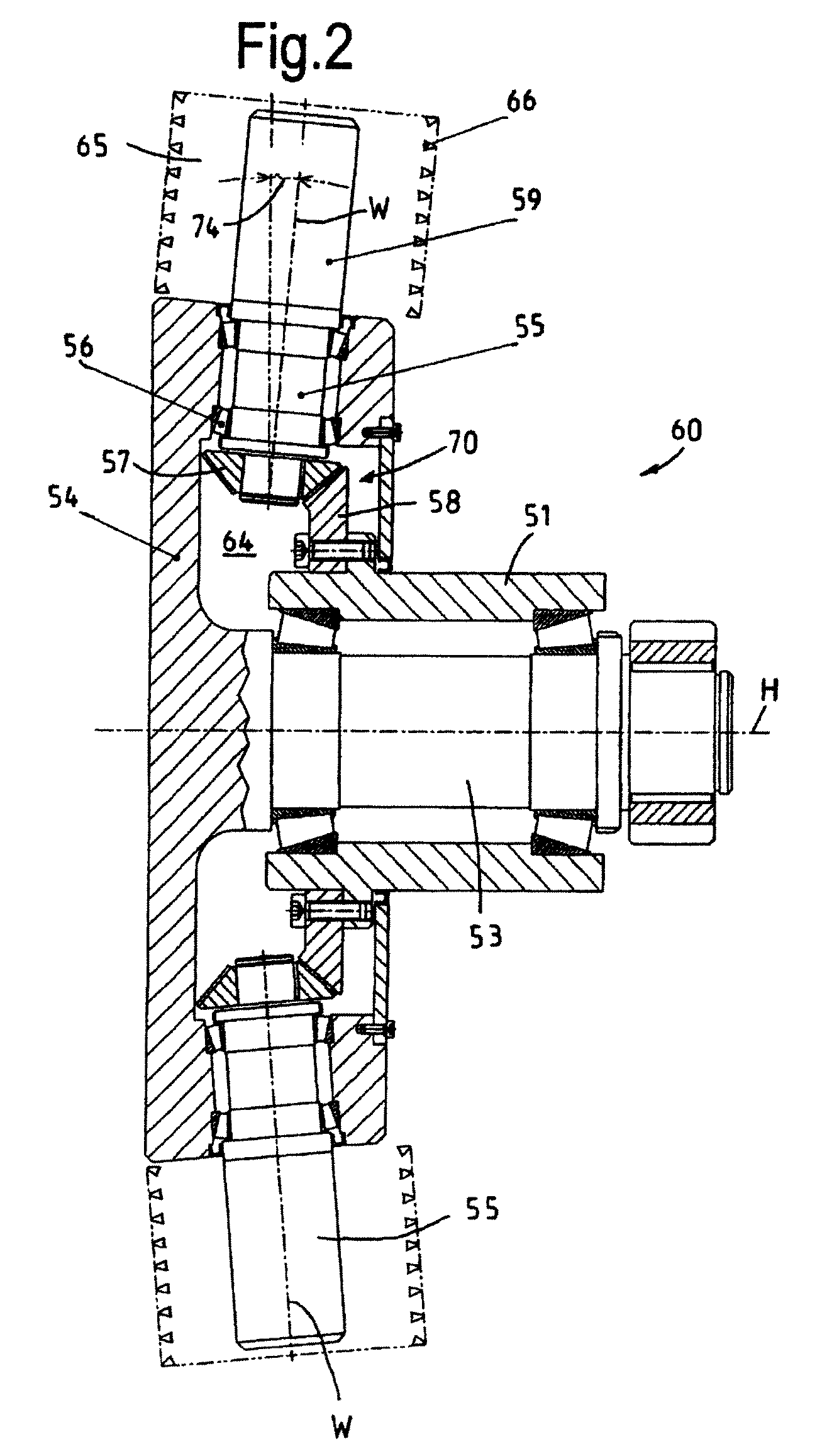
[0015]It is advantageous, further, if each cutting tool arranged on a tool shaft is arranged, in relation to the arrangement of a cutting tool of a tool shaft lying in front of or behind it in the drum circumferential direction, so as to be offset by an angular amount and / or at a distance from the drive shaft or drum axis. The cutting tools are in this case preferably formed on or fastened to tool carriers which are connected releasably to the tool shafts. Alternatively, however, they could also be anchored directly to the ends of the tool shafts. In order to make it easier to exchange the tool shafts, these may be received in bearing bushes rotatably by means of bearings, and so as to be sealed off by means of shaft seals, and what is achieved in a relatively simple way by this is that the tool shafts can be inserted and locked exchangeably in a cartridge-like manner by means of the bearing bushes in drum chambers provided on the tool drum.
[0018]For using the apparatus according to the invention in underground mining for the extraction of coal, it may be particularly advantageous if the tool drum is provided between adjacent tool shafts with radially extending scrapers or shovels, by means of which the material preferably released at the working face by means of undercutting cutting tools is loaded into a conveyor or the like of the extraction device.
[0020]It is also advantageous if the rotary drive takes place by means of variable drives, so that different rotational speeds can be set continuously, even without an interruption in the cutting work. A corresponding design of the apparatus makes it possible that the respective drive-specific requirements can be adapted to the geometry of the surface to be cut and to the properties of the material to be cut or to be removed.

Problems solved by technology

On account of the relatively long contact times between the cutting tools and the material to be broken down, the wear even of cutting tools provided with hard metal tips is high especially where hard materials to be broken down are concerned.
In the case of apparatuses operating by impact overlap, the mounting of the individual elements of the apparatus and also noise pollution sometimes present considerable problems.
What can be achieved by the overlapping of the rotational movements of the tool drum and of the tool spindles is that only relatively few cutting tools are simultaneously in operative engagement with the material to be milled or to be removed, thus resulting in a high releasing force for each individual cutting tool.
However, in the removal of the materials on closed surfaces, but also in the drilling open of core drillholes or the like, entry by virtue of a feed movement of the apparatus into the material to be removed sometimes presents problems and is sometimes impossible.
Furthermore, the breakdown of materials on a large surface requires a considerable diameter of the tool drum, thus resulting in a comparatively high overall weight of the apparatus.

Method used


Image

  • Method and apparatus for the milling cutting of materials
  • Method and apparatus for the milling cutting of materials
  • Method and apparatus for the milling cutting of materials

Examples


Embodiment Construction

[0034]Referring now to the drawings wherein the showings are for the purpose of illustrating preferred and alternative embodiments of the invention only and not for the purpose of limiting same,

[0035]Reference symbol 10 in FIG. 1 illustrates, as a whole, an apparatus according to the invention, for example for removal of coverings in roadbuilding, for the renovation of floors or walls in building construction or for use in mining, according to a first variant. The apparatus 10 comprises a drum carrier 1 which may be fastened to a suitable holding device or movement device for the apparatus 10, for example to the boom of an excavator, to the machine boom of an advance working machine or the like. The tubular, here hollow drum carrier 1 has a central bearing receptacle 11 which is designed centrically to the drum axis or main axis H and in which a drive shaft 3 connected fixedly in terms of rotation to a tool drum 4 is mounted freely rotatably by means of two tapered roller bearings 2...


PUM


Abstract

An apparatus for the milling and / or drilling cutting of materials, in particular for the removal of rock, minerals or coal, with a tool drum which is mounted on a drum carrier rotatably about a drum axis, in which a plurality of tool shafts, which carry cutting tools at their ends projecting from the tool drum, are rotatable drivable mounted, at least two of the tool shafts being drivable by a common gear drive which has power take-off gearwheels arranged fixedly in terms of rotation on the tool shafts, and a common drive element which cooperates with the power take-off gearwheels. The drive element and the tool drum being rotatable in relation to one another and the shaft axes of the tool shafts standing transversely to the drum axis.

Description

[0001]This application claims priority to and the benefit of the filing date of International Application No. PCT / EP2007 / 007600, filed Aug. 30, 2007, which application claims priority to and the benefit of the filing date of German Application No. 10 2006 040881.0, filed Aug. 31, 2006, both of which are hereby incorporated by reference into the specification of this application.[0002]The invention relates to an apparatus for the milling and / or drilling cutting of materials, in particular for the removal of rock, minerals or coal, with a tool drum which is mounted on a drum carrier rotatably about a drum axis, in which a plurality of tool shafts, which carry cutting tools at their ends projecting from the tool drum, are mounted so as to be capable of being driven in rotation, at least two of the tool shafts being drivable by a common gear drive which has power take-off gearwheels, arranged fixedly in terms of rotation on the tool shafts, and a common drive element which cooperates wi...

Claims


Application Information

Patent Timeline
Patent Type & Authority Patents(United States)
IPC IPC(8): E21C27/22
CPCE21C27/22
Inventor BECHEM, ULRICH
Owner CATERPILLAR INC
Why Eureka
Try Eureka