Power supply methods and systems

a power supply and power supply technology, applied in the direction of dc network circuit arrangement, ac network voltage adjustment, efficient power electronics conversion, etc., can solve the problems of high cost of switching logic circuitry, high monetary cost, space consumption,

Active Publication Date: 2011-03-01
UNICOM ENG INC
View PDF9 Cites 42 Cited by
  • Summary
  • Abstract
  • Description
  • Claims
  • Application Information

AI Technical Summary

Benefits of technology

[0010]Related aspects of the invention provide such a power supply as described above including three or more rectifier circuits (e.g., PFCs) of the type described above. Each such additional rectifier circuit is configured to receive an AC input and to gene

Problems solved by technology

Such switching circuitry can be complicated, requiring multiple relays, as well as processing logic, to detect power source failures and to effect swit

Method used


Image

  • Power supply methods and systems
  • Power supply methods and systems
  • Power supply methods and systems

Examples


Embodiment Construction

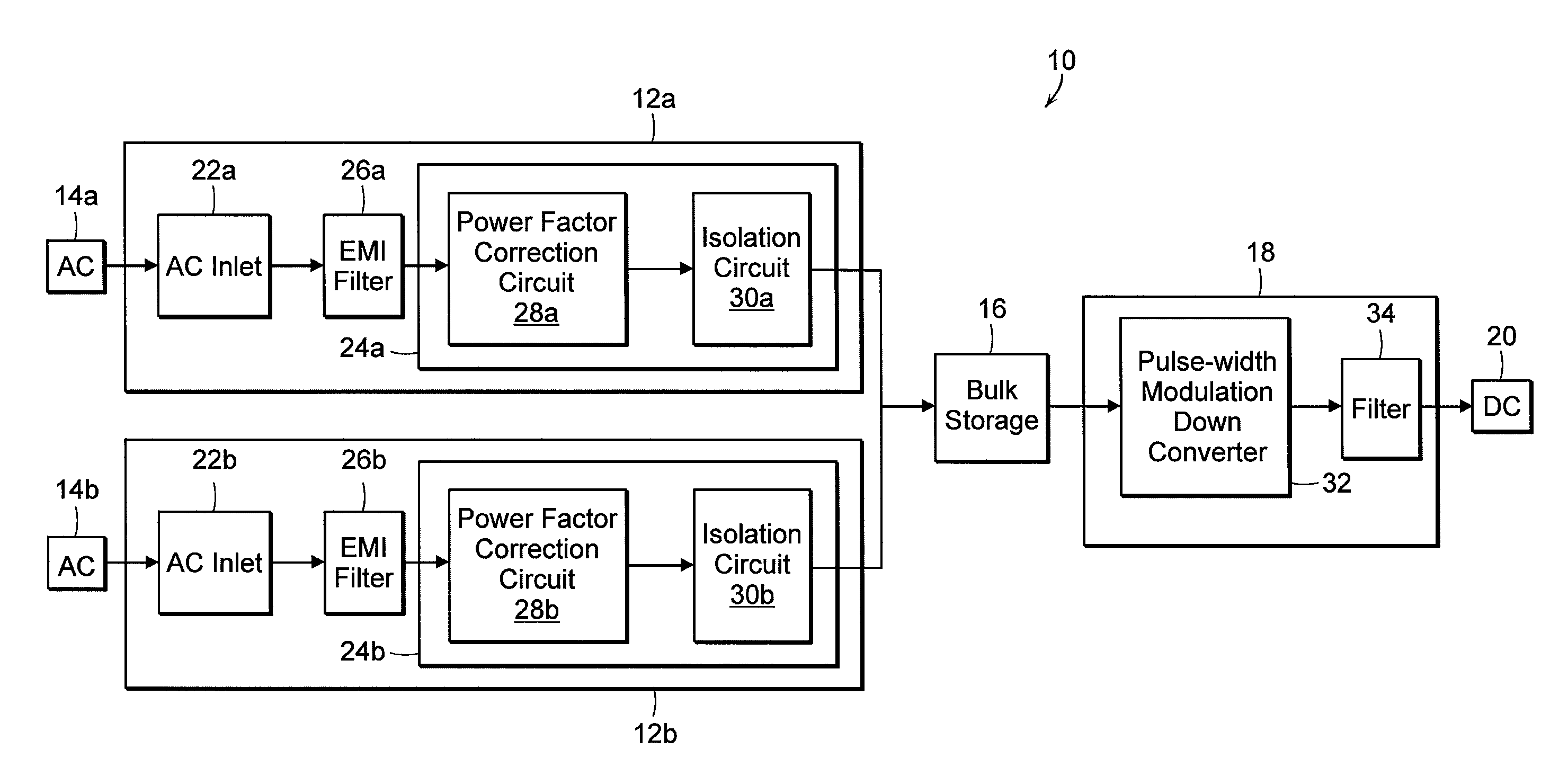
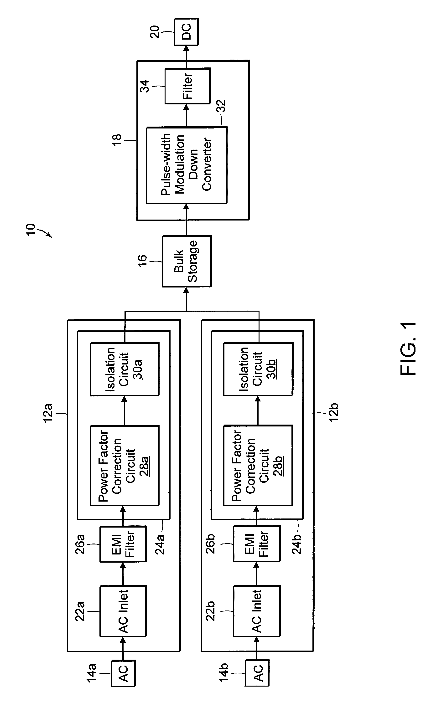
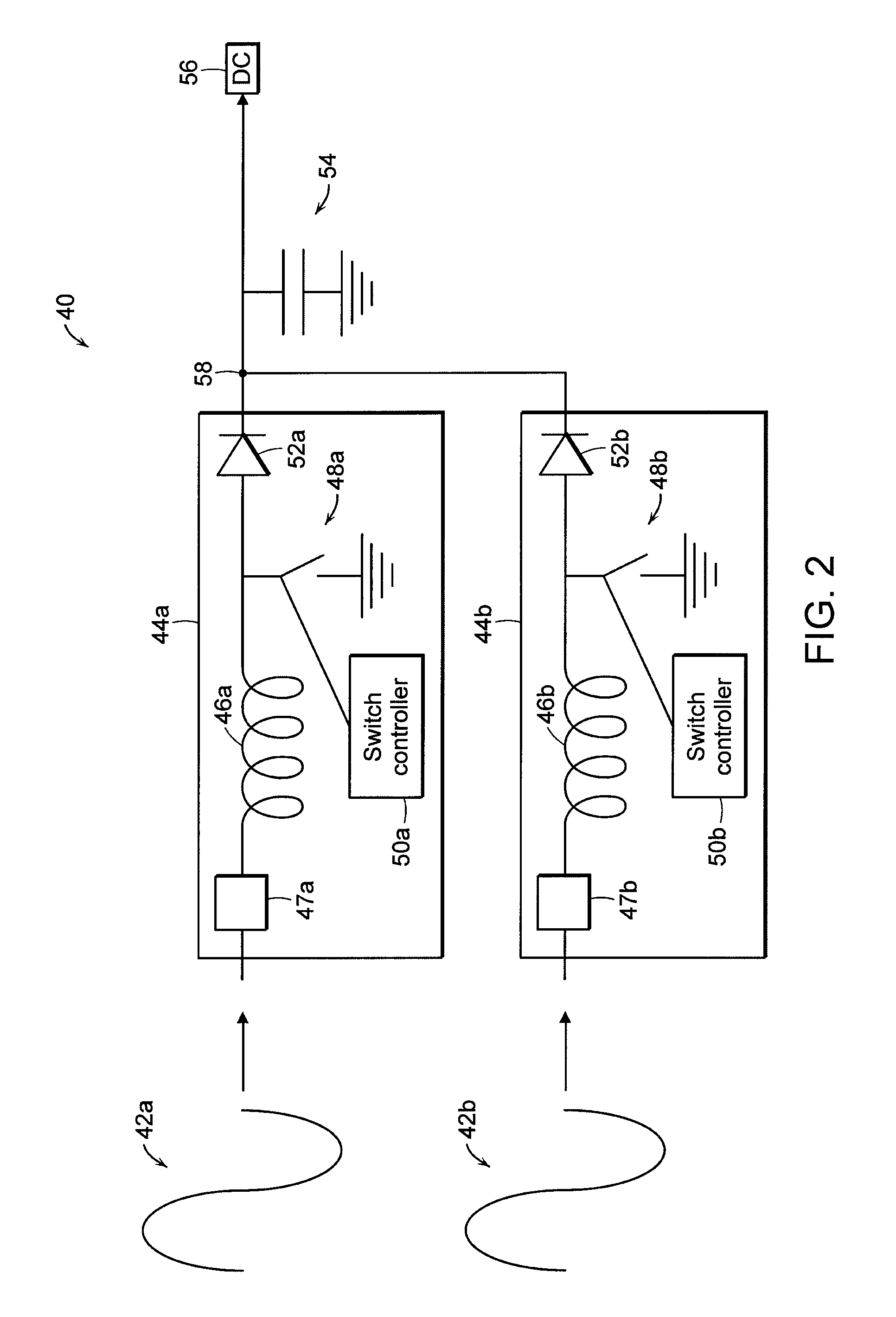
[0023]FIG. 1 illustrates a power supply 10 according to one practice of the invention. The illustrated power supply 10 includes first and second power supply front ends 12a, 12b each configured to charge a storage unit 16 from AC power received from first and second sources 14a, 14b. The storage unit 16, e.g., a bulk capacitor, releases the stored charge to a back end 18 for output 20 as DC power to one or more electronic devices—e.g., the componentry of a rack-mounted appliance of a digital data processor. The elements 12-18 are generally coupled as shown in the drawing and as discussed further below. Those skilled in the art will appreciate that the supply 10 shown in FIG. 1, and power supplies 40, 60 illustrated in FIGS. 2 and 3 and discussed below, are just examples of the invention and that other power supplies according thereto can include more or fewer elements electronically coupled together as shown, or otherwise.

[0024]Turning back to FIG. 1, the AC sources 14a, 14b are con...


PUM


Abstract

The invention provides, in some aspects, a power supply that includes a first rectifier circuit configured to receive a first AC input and to generate a first DC output, a second rectifier circuit configured to receive a second AC input and to generate a second DC output, and a storage unit (e.g., a capacitor) configured to store charge from both the first DC and the second DC outputs. The storage unit can itself be configured to supply that stored charge as DC power, e.g., to a computer or other coupled device.

Description

BACKGROUND OF THE INVENTION[0001]Electronic devices, such as computers and their various internal components (e.g., microprocessors, memory boards, disk drives, etc.) require power. The typical source is a 110-120 volt or 220-240 volt alternating current (AC) feed, supplied by a utility company. In many devices, the AC current is converted into direct current (DC) for use by internal components.[0002]In instances where nonstop operation is critical, electrical devices may be fed by multiple power sources and / or provisioned with multiple power supplies to guard against inadvertent power loss. Servers and other enterprise computers are an example.[0003]One way to supply redundant power is through multiple (usually, two) feeds from separate AC sources to the device requiring power. In this way, loss of one AC source does not force shutdown of the device. However, to ensure continuous power, the device must be equipped to switch between the AC sources quickly enough to avoid even tempor...

Claims


Application Information

Patent Timeline
IPC IPC(8): H02J3/16
CPCH02J1/102H02M7/23H02M1/4225H02M3/1584Y02B70/126Y02B70/10
Inventor PISTEL, CHRIS
Owner UNICOM ENG INC
Why Eureka
Try Eureka