Brushless disk DC motor

a brushless, disk technology, applied in the direction of magnetic circuit rotating parts, magnetic circuit shape/form/construction, transportation and packaging, etc., can solve the problems of low peak power density, heavy and unresponsive motors, and difficult control of speed, so as to minimize resistive power loss reduce power and torque, and minimize eddy current and resultant heat loss

Inactive Publication Date: 2011-03-01
SHAW BILL S
View PDF19 Cites 44 Cited by
  • Summary
  • Abstract
  • Description
  • Claims
  • Application Information

AI Technical Summary

Benefits of technology

[0005]In accordance with the illustrated preferred embodiment of the present invention, a brushless DC motor employs a flat circular non-ferrous stator plate having a plurality of electromagnets mounted in a ring pattern on an inner face thereof. A plurality of permanent magnets are mounted in equal numbers in inner and outer ring patterns on the outer and inner cylindrical surfaces, respectively, of a pair of steel rotors of different diameter that rotate in concert. The stator plate and the pair of rotors are axially and diametrically aligned such that the inner ring of permanent magnets rotates in close proximity to and inside the ring of electromagnets, and the outer ring of permanent magnets rotates in close proximity to and outside the ring of electromagnets. The electromagnets utilize tape-wound amorphous metal cores to minimize eddy currents and resultant heat losses and to permit the use of heavier gauge copper windings to minimize resistive power losses and attendant heat. The DC motor of the present invention is capable of accommodating a larger number of poles, in the form of permanent magnets, than prior ar...

Problems solved by technology

These motors suffer from low peak power densities on the order of 0.3 horsepower/pound.
Thus, they are heavy and unresponsive, as a typical 40-horsepower motor weighs 130 pounds.
They are not sealed, since air flow through the motor is required...

Method used


Image

  • Brushless disk DC motor
  • Brushless disk DC motor
  • Brushless disk DC motor

Examples


Embodiment Construction

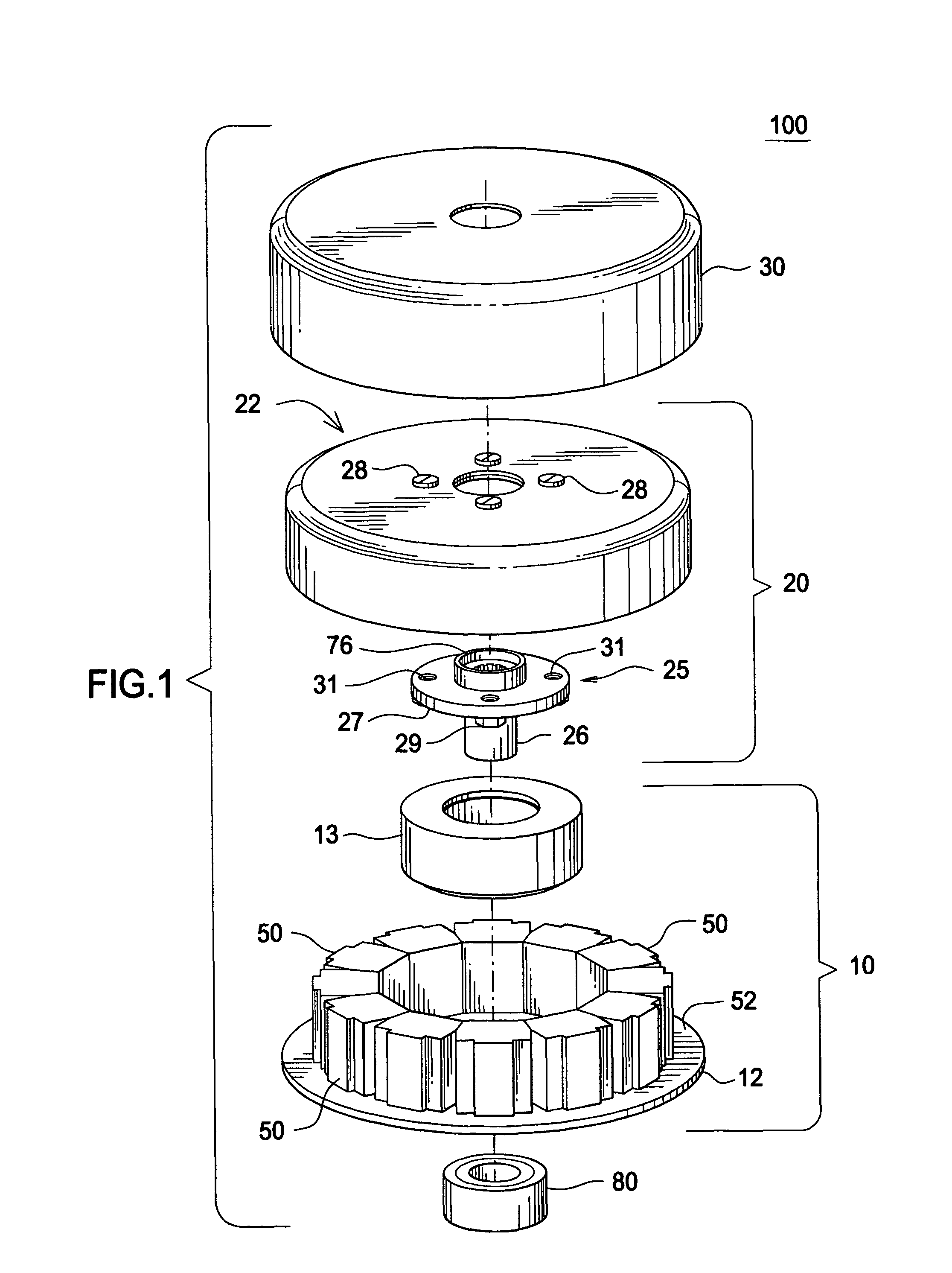
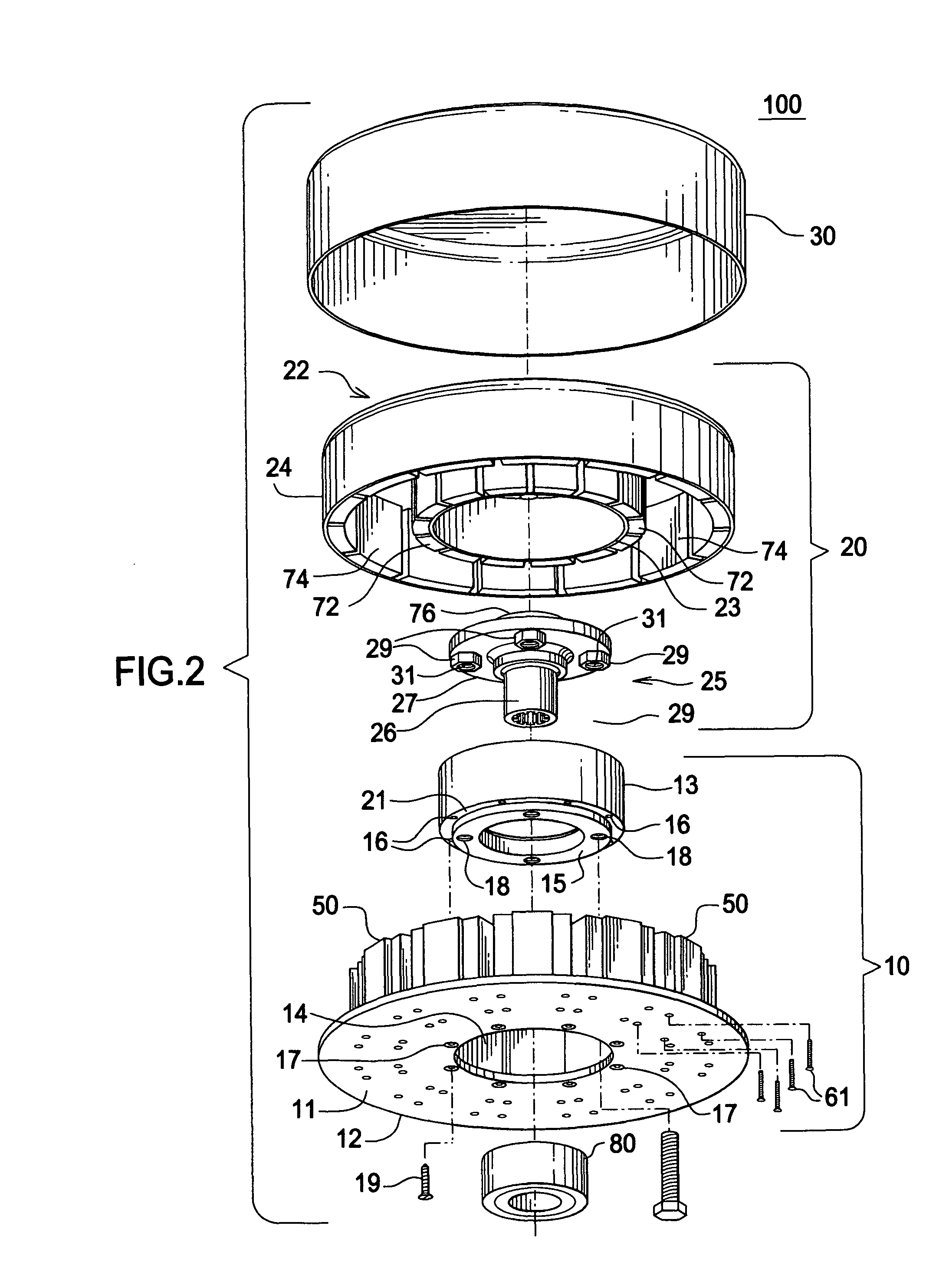
[0014]Referring now generally to FIGS. 1-6, there is shown a motor 100, in accordance with the present invention, that includes a stator assembly 10, a rotor assembly 20, a cover 30, and a bearing 80, all axially aligned. Stator assembly 10 includes a stator plate 12 fabricated as a flat disc of non-ferrous material such as aluminum or copper having a central circular opening 14 therein. A cylindrical stator hub 13 has a stator end of reduced outer diameter that fits into central opening 14 in stator plate 12 such that an inner face 15 of the stator end of stator hub 13 is flush with an outer surface 11 of stator plate 12. Stator hub 13 is bolted in that position to stator plate 12 by means of a plurality of bevel-headed bolts 19 inserted through countersunk bolt holes 17 in stator plate 12 and into threaded 12 bolt holes 16 in an outer step face 21 of the stator end of stator hub 13. Threaded bolt holes 18 provided in the inner face 15 of the stator end of stator hub 13 facilitate ...


PUM


Abstract

A brushless disk DC motor that exhibits high power density and light weight and is capable of power regeneration and reverse operation employs a flat circular non-ferrous stator plate having a plurality of electromagnets mounted in a ring pattern on an inner face thereof. Permanent magnets are mounted in equal numbers in inner and outer ring patterns on the outer and inner cylindrical surfaces, respectively, of a pair of steel rotors of different diameter that rotate in concert. The stator plate and the pair of rotors are axially aligned such that the inner and outer rings of permanent magnets rotate adjacent to and inside and outside, respectively, the ring of electromagnets. The electromagnets utilize tape-wound amorphous metal cores to minimize eddy currents and resultant iron losses and to permit the use of heavier gauge copper windings to minimize resistive power losses. A greater number of poles in the form of permanent magnets can be accommodated, the number being limited only by the diameter of the rotor, thus providing increased power and torque over prior art brushless DC motors having a limited number of poles. The present motor exhibits up to 200% more starting torque, thus eliminating the need for a gear box or clutch in electric vehicle applications.

Description

BACKGROUND AND SUMMARY OF THE INVENTION[0001]This invention relates generally to DC motors and, more particularly, to a highly efficient, sealed, brushless, disk DC motor having inner and outer rings of permanent magnets mounted on cylindrical surfaces of outer and inner rotors, respectively, and having a ring of electromagnets mounted on a stator such that inwardly facing surfaces of the permanent magnets rotate in close proximity to adjacent opposite surfaces of the ring of electromagnets.[0002]Variable speed electric motors of different types have been employed in a variety of applications over the years, most recently in electric vehicles. One such motor is the series DC motor, which employs brushes and wound coils. These motors suffer from low peak power densities on the order of 0.3 horsepower / pound. Thus, they are heavy and unresponsive, as a typical 40-horsepower motor weighs 130 pounds. They are not sealed, since air flow through the motor is required to cool the rotor, and...

Claims


Application Information

Patent Timeline
IPC IPC(8): H02K16/00
CPCH02K1/148H02K1/185H02K1/187H02K21/16H02K21/222H02K1/30Y02T10/641Y02T10/64
Inventor SHAW, BILL S.
Owner SHAW BILL S
Why Eureka
Try Eureka