Centralized call processing

a call processing and central processing technology, applied in the field can solve the problems of large number of call processing systems, equipment costs, and not new, and achieve the effects of facilitating low latency data communication, high capacity, and low connection cos

Inactive Publication Date: 2011-03-01
SECURUS TECH LLC
View PDF312 Cites 198 Cited by
  • Summary
  • Abstract
  • Description
  • Claims
  • Application Information

AI Technical Summary

Benefits of technology

[0013]Centralized call processing platforms of preferred embodiments of the present invention comprise high capacity and high speed routing / switching functionality, such as a router and gigabit Ethernet switch, to facilitate low latency data communication between call processing functionality and / or PSTN interfacing functionality of the call processing platform and call processing gateways of a plurality of facilities. Call processing functionality of embodiments of a call processing platform may be provided by a plurality of servers operable under control of instruction sets defining operation to provide call processing features such as calling party identification, call validation, call routing, etcetera. PSTN interfacing functionality of embodiments of a call processing platform may be provided as a data connection (e.g., media gateway control protocol (MGCP) or session initiation protocol (SIP)) to the PSTN. Additionally or alternatively, PSTN interfacing functionality of embodiments of a call processing platform may be provided as POTS trunking or other more traditional telephone line interface. Preferred embodiments, however, may place calls on the PSTN in VoIP protocols to receive the benefit of such advantages as lower connection cost offered by the carrier when introduced to the PSTN in VoIP protocols, reduced latencies associated with repeated conversion of the call between VoIP and analog protocols, and improved call quality associated with carrying the call in digital format closer to the called party before conversion back to analog.

Problems solved by technology

Automated systems for providing call processing functions are not new.
The aforementioned locally disposed call processing systems provide a number of disadvantages in addition to the equipment costs associated with such a configuration.
For example, a large number of call processing systems, particularly when distributed throughout a large geographic area, presents challenges from a maintenance standpoint.
However, merely establishing such dial-up connections with a large number of remote systems is burdensome, even ignoring the time and effort required in actually providing the update.
Even where a persistent data link is maintained between such an OAM&P terminal and the remote systems, managing an update of a large number of remote systems is difficult.
Additionally, data sharing, aggregation, and statistical analysis available using such discrete or distributed call processing systems is very limited.
The distributed and discrete nature of such previous configurations is not well suited for widespread data sharing, aggregation, and analysis.
Moreover, the lack of persistent and / or high bandwidth data connections, such as in the case of the typical dial-up configuration, does not readily facilitate the aggregation of large amounts of data as might otherwise be useful in developing an image across many facilities for which calling services are provided.
Introducing new features and functions in such call processing systems can be problematic.
Additional challenges may be presented with respect to use of the aforementioned discrete or distributed call processing systems in particular situations.
Recording calls typically require substantial recording media space.
Where such call processing systems are used in providing collect calling or other subsequently billed calling services, discrete or distributed call processing system configurations can present issues with respect to billing and / or risk management.
Moreover, analysis with respect to call velocity (information with respect to a number of calls placed to or from a particular number over a period of time) and / or credit limits may not be possible until the aforementioned periodic collection of data, allowing calls which otherwise would not be allowed to be completed to continue to be placed during the time of a polling period.

Method used


Image

  • Centralized call processing
  • Centralized call processing
  • Centralized call processing

Examples


Embodiment Construction

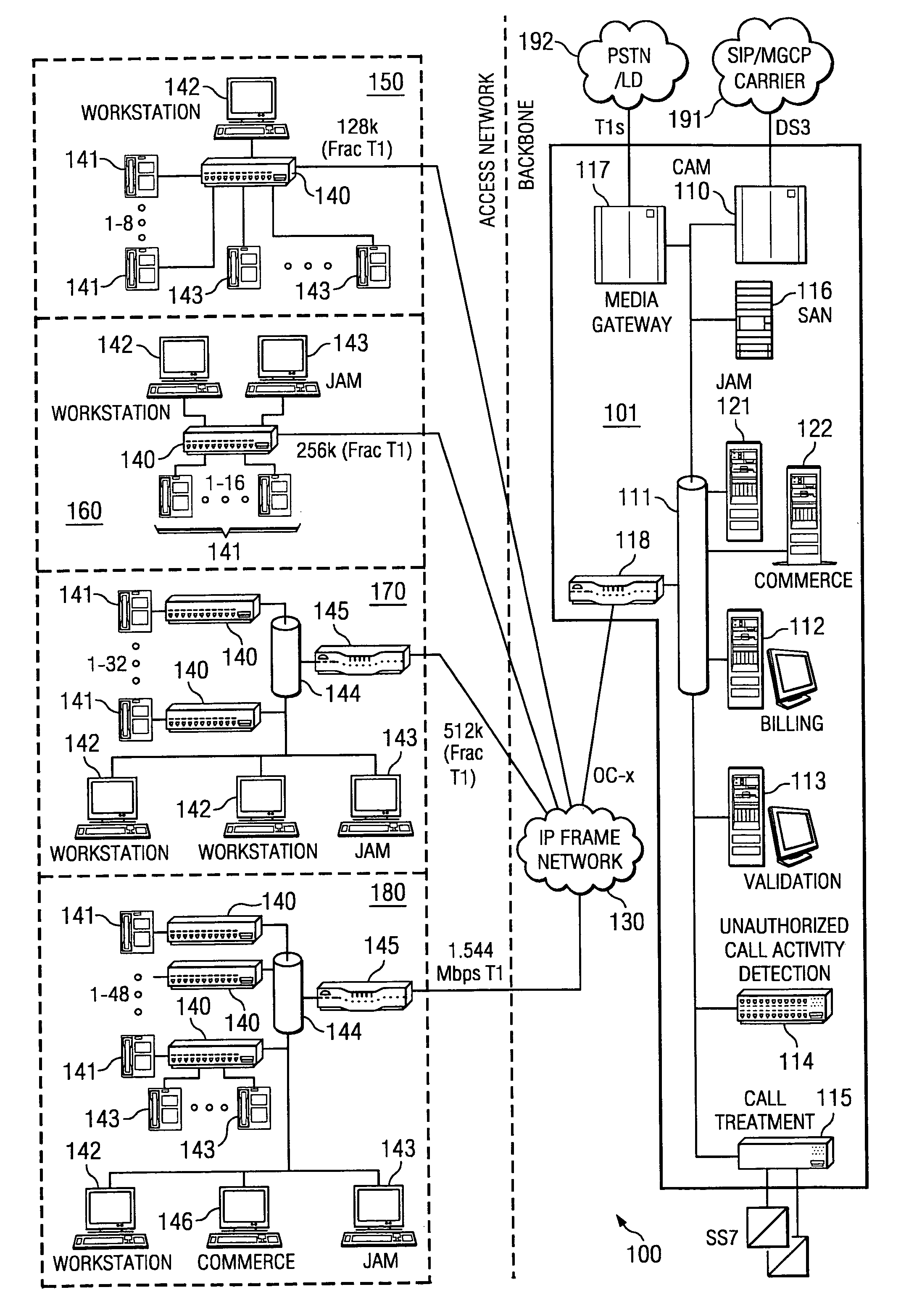
[0021]Directing attention to FIG. 1, an embodiment of a centralized or nodal call processing system according to the present invention is shown as call processing system 100. Call processing system 100 of the illustrated embodiment includes call processing platform 101 in communication with facilities 150-180 via network 130. It should be appreciated that, although only a single call processing platform is represented in FIG. 1, any number of call processing platforms, perhaps having varied configurations and / or disposed at different geographic locations, may be implemented with respect to a call processing system of the present invention. Likewise, the number and configurations of facilities for which calling services may be provided by a call processing system of the present invention is not limited to that shown in FIG. 1.

[0022]To better aid the reader in understanding the concepts of the present invention, call processing system 100 of FIG. 1 is described herein with reference t...


PUM


Abstract

Disclosed are systems and methods which provide a centralized architecture for call processing. Embodiments utilize voice over Internet protocols (VoIP) to carry calls from a location at which calling services are provided to a centralized call processing platform providing call processing functionality, such as calling party identification, call validation, call routing, and connection to the public switched telephone network (PSTN). Call processing gateways may be utilized to provide plain old telephone service (POTS) analog line interfaces for use with a plurality of telephone sets disposed for use at a location and at least one wide area network (WAN) interface for providing high speed data communication to a centralized call processing platform. PSTN interfacing by a call processing platform may be provided as a VoIP connection to the PSTN and/or as POTS trunking. Call processing platforms may provide for data sharing, aggregation, and/or analysis across multiple facilities served.

Description

CROSS-REFERENCE TO RELATED APPLICATIONS[0001]The present application is related to co-pending and commonly assigned U.S. patent application Ser. No. 10 / 135,878 entitled “Information Management and Movement System and Method,” filed Apr. 29, 2002, Ser. No. 10 / 135,883 entitled “Optimizing Profitability in Business Transactions,” filed Apr. 29, 2002, Ser. No. 10 / 190,315 entitled “System and Methods for Offering a Service to a Party Associated with a Blocked Call,” filed Jul. 3, 2002, Ser. No. 09 / 640,831 entitled “System and Method for Reverse Billing of a Telephone Call,” filed Aug. 17, 2000, Ser. No. 10 / 022,946 entitled “Method for Determining an Entity Responsible for Billing a Called Party,” filed Dec. 17, 2001, Ser. No. 10 / 217,149 entitled “System and Method for Call Treatment,” filed Aug. 12, 2002, Ser. No. 10 / 252,956 entitled “Three-Way Telephone Call Prevention System and Method,” filed Sep. 20, 2002, Ser. No. 09 / 995,253 entitled “Method and Apparatus for Exchanging Data Between...

Claims


Application Information

Patent Timeline
Patent Type & Authority Patents(United States)
IPC IPC(8): H04M3/00
CPCH04M3/38H04M7/006H04M3/2281H04M7/0078H04M2207/20
Inventor RAE, ROBERT L.
Owner SECURUS TECH LLC
Why Eureka
Try Eureka