Silicon based condenser microphone and packaging method for the same

a condenser microphone and silicon-based technology, applied in the field of condenser microphones, can solve the problems of deterioration of bonding properties and increase of manufacturing costs, and achieve the effect of increasing bonding strength and high resistance to external nois

Inactive Publication Date: 2011-03-08
BSE CO LTD
View PDF3 Cites 125 Cited by
  • Summary
  • Abstract
  • Description
  • Claims
  • Application Information

AI Technical Summary

Benefits of technology

[0007]Accordingly, in order to solve the problems, the present invention provides a silicon based condenser microphone for increasing bonding strength and having high resistance to external noise such as electromagnetic waves by welding an opened end of a metal case to a substrate which is mounted with MEMS microphone parts and a packaging method for the silicon based condenser microphone.

Problems solved by technology

Thus, the conventional packaging method has problems in that a manufacturing cost is raised and a bonding property is deteriorated due to a complex process, and the method is sensitive to external noise such as an electromagnetic wave noise and the like since a non conductive material unlike a metal housing is used.

Method used


Image

  • Silicon based condenser microphone and packaging method for the same
  • Silicon based condenser microphone and packaging method for the same
  • Silicon based condenser microphone and packaging method for the same

Examples


embodiment 1

Modification 1 of Embodiment 1

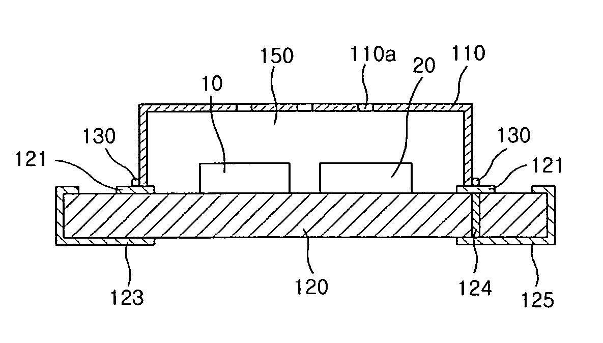
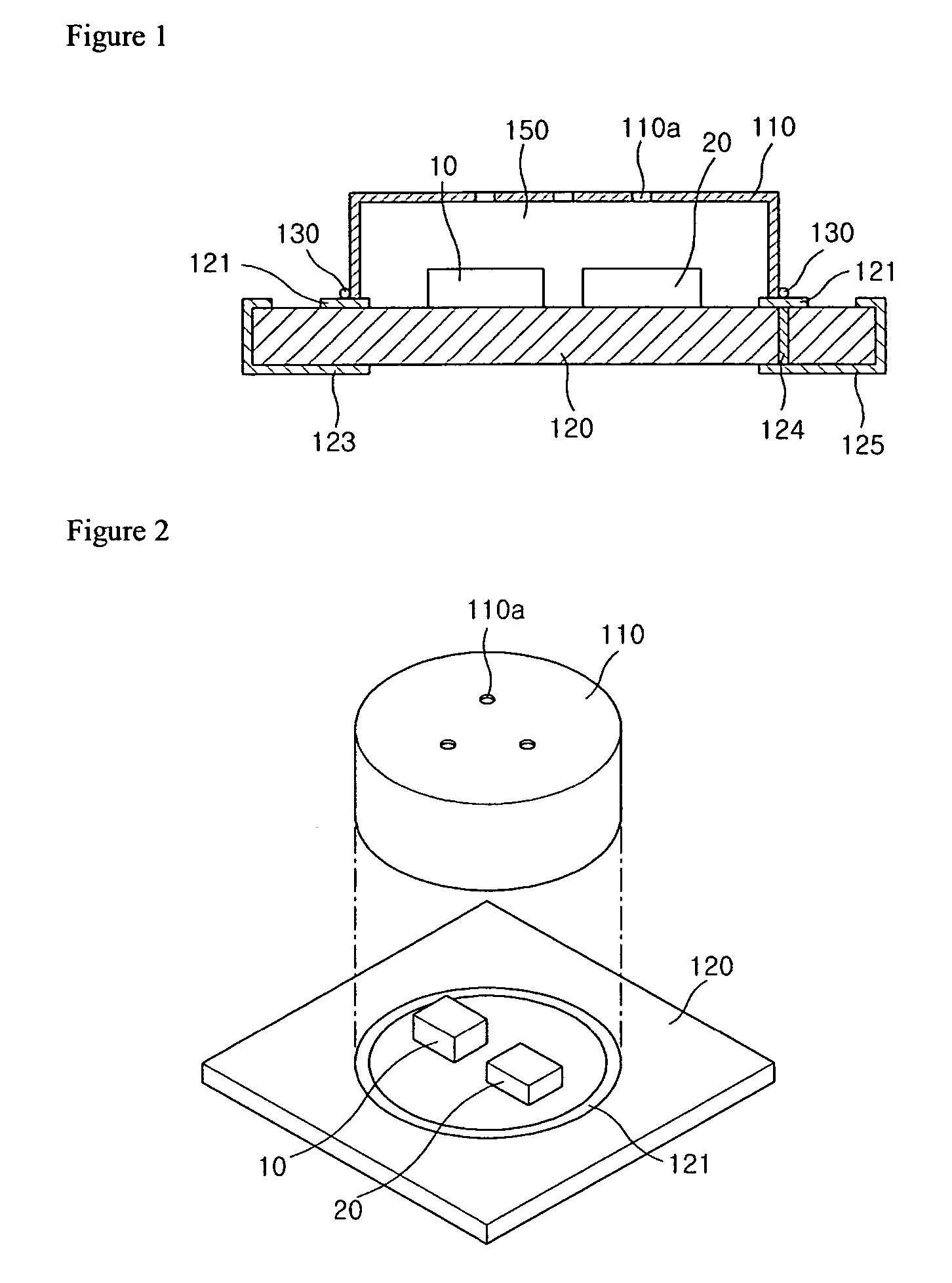
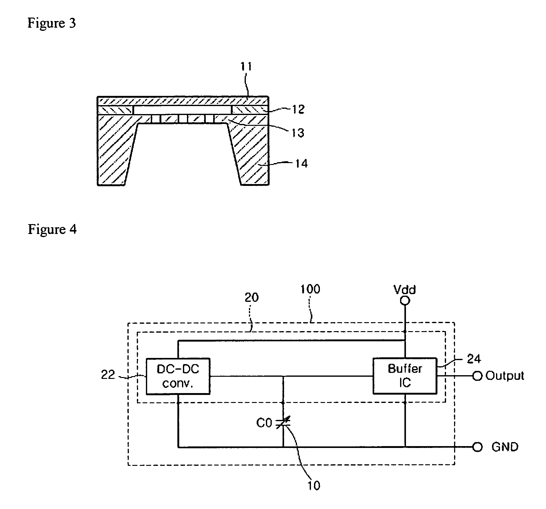
[0038]FIG. 1 is a sectional side view of a first modification of a first embodiment according to the present invention, FIG. 2 is an exploded perspective view of a first modification of a first embodiment according to the present invention, FIG. 3 is a view showing an example of a structure for a MEMS chip of a silicon based condenser microphone applied to each embodiment of the present invention in common, and FIG. 4 is a circuit diagram of a silicon based condenser microphone according to the present invention.

[0039]According to a first modification of a first embodiment, as shown in FIGS. 1 and 2, a cylindrical metal case 110 is welded to a PCB 120 which is mounted with a MEMS chip 10 and an ASIC chip 20 by a laser.

[0040]Referring to FIGS. 1 and 2, the PCB 120 is mounted with the MEMS chip 10 and the ASIC chip 20 and is formed with a circular connecting pattern 121 on a portion which contacts the metal case 110. Meanwhile, if necessary, the PCB 120 m...

embodiment 2

Modification 1 of Embodiment 2

[0069]FIG. 10 is a sectional side view of a first modification of a second embodiment according to the present invention, FIG. 11 is a sectional side view showing that a microphone shown in FIG. 10 is mounted on a main PCB, and FIG. 12 is an exploded perspective view of a first modification of a second embodiment according to the present invention.

[0070]According to a first modification of a second embodiment according to the present invention, as shown in FIGS. 10 and 12, there is provided an example that a cylindrical metal case 110 is welded to a PCB 120 which is mounted with a MEMS chip 10 and an ASIC chip 20 by a laser.

[0071]Referring to FIGS. 10 and 12, the PCB 120 is formed with a sound hole 120a for collecting an external sound near the center thereof and is mounted with the MEMS chip 10 and the ASIC chip 20 around the center thereof. Further, the PCB is formed with a circular connecting pattern 121 on its portion which contacts the metal case 1...

modification 5

of Embodiment 2

[0090]FIG. 16 is a sectional side view of a fifth modification of a second embodiment according to the present invention, wherein a PCB is formed with a sound hole on a portion where a MEMS chip is positioned.

[0091]Referring to FIG. 16, the metal case 110 is firmly attached to the connecting pattern 121 of the PCB 120 which is mounted with the MEMS chip 10 and the ASIC chip 20 by laser welding.

[0092]Further, the PCB 120 is formed with the sound hole 120a for collecting an external sound on a position where the MEMS chip 10 is mounted, and is formed with the sealing terminal 120a for sealing the sound hole 120a by soldering on the outside of the sound hole to prevent distortion of a sound wave in a space between the main PCB 300 and the microphone. Further, the PCB 120 may be formed with the connecting terminals 123 and 125 for connecting with the external device on a bottom surface thereof, wherein the number of the connecting terminals 123 and 125 may be two to eight...


PUM


Abstract

Disclosed are a silicon based condenser microphone and a packaging method for the silicon based condenser microphone. The silicon based condenser microphone comprises a metal case, and a board which is mounted with a MEMS microphone chip and an ASIC chip having an electric voltage pump and a buffer IC and is formed with a connecting pattern for bonding with the metal case, wherein the connecting pattern is welded to the metal case. The method for packaging a silicon based condenser microphone includes the steps of inputting a board which is mounted with a MEMS chip and an ASIC chip and is formed with a connecting pattern; inputting a metal case, aligning the metal case on the connecting pattern of the board, and welding an opened end of the metal case to the connecting pattern of the board. Thus, the metal case is welded to the board by the laser.

Description

TECHNICAL FIELD[0001]The present invention relates to a condenser microphone, and, more particularly, to a silicon based condenser microphone which packages a silicon microphone chip fabricated by a MEMS technology to increase a mechanical firmness and enhance effects for preventing noise from entering the microphone and a packaging method for the silicon based condenser microphone.BACKGROUND ART[0002]Generally, a condenser microphone which has been widely used in mobile equipment or audio equipment consists of a voltage bias element, a pair of a diaphragm and a back plate for forming a capacitor which is changed corresponding to sound pressure, and a JFET for buffering an output signal. This typical condenser microphone has an assembly which is integrally assembled by inserting a diaphragm, a spacer ring, an insulating ring, a back plate, a conductive ring and a PCB into a case.[0003]Recently, a semiconductor fabricating technology using a micromachining technology has been introdu...

Claims


Application Information

Patent Timeline
Patent Type & Authority Patents(United States)
IPC IPC(8): H04R25/00
CPCB81C1/0023H04R19/04H04R31/006B81B2201/0257H04R1/06H04R2499/11H01L2924/16152
Inventor SONG, CHUNG DAM
Owner BSE CO LTD
Why Eureka
Try Eureka