Winch system for VTOL aircraft

a technology for vertical takeoff and landing and vtol aircraft, which is applied in the direction of aircraft, transportation and packaging, hoisting equipment, etc., can solve the problems of not providing the relatively large angle and short cable lengths necessary to meet future requirements

Inactive Publication Date: 2011-03-22
SIKORSKY AIRCRAFT CORP
View PDF4 Cites 18 Cited by
  • Summary
  • Abstract
  • Description
  • Claims
  • Application Information

AI Technical Summary

Benefits of technology

[0007]The traction winch system according to the present invention generally includes a cable storage system, a drive system and a deployment system to deploy a cable having a hook system attached to an end segment thereof. The traction winch system provides low-cable tension which increases the accuracy and repeatability of a level wind to provide gentle spooling and increases cable life. In addition, the low cable tension eliminates the tendency to bury the outer layer of rope into the previous layer (a trend known as knifing) which also increases cable life by avoiding wear-inducing piling.
[0009]The dual mode transmission provides high speed capabilities when moderate to no load is being lifted, while also providing the high torque necessary for heavy lift operations at low speeds. The drive system is capable of hoisting a 40.0-ton load at 1.0 fps winch rate as well as a 22.4-ton load at 2.0 fps winch rate.
[0010]Torque (cable pull) and RPM (cable speed) are transferred through the deployment system which is located on an output side of the drive system. The deployment system is rated to support a maximum hook load and is mounted to the airframe for pivotable movement about a deployment axis generally transverse to the aircraft longitudinal axis. From the deployment system, the cable exits the aircraft. This configuration provides significant cable exit angles, both lateral and longitudinally while contributing to the systems load-out flexibility.
[0013]The present invention therefore provides a compact and relatively lightweight winch system capable of future load requirements which can be readily packaged within a VTOL aircraft for quad operation with relatively large cable angle direction change.

Problems solved by technology

This is adequate for conventional, centrally aligned lift operations with minimal cable angle direction change, but cannot provide relatively large angles and short cable lengths necessary to meet future requirements in which a multiple of winch systems are attached to payloads expected of the future requirements.

Method used


Image

  • Winch system for VTOL aircraft
  • Winch system for VTOL aircraft
  • Winch system for VTOL aircraft

Examples


Embodiment Construction

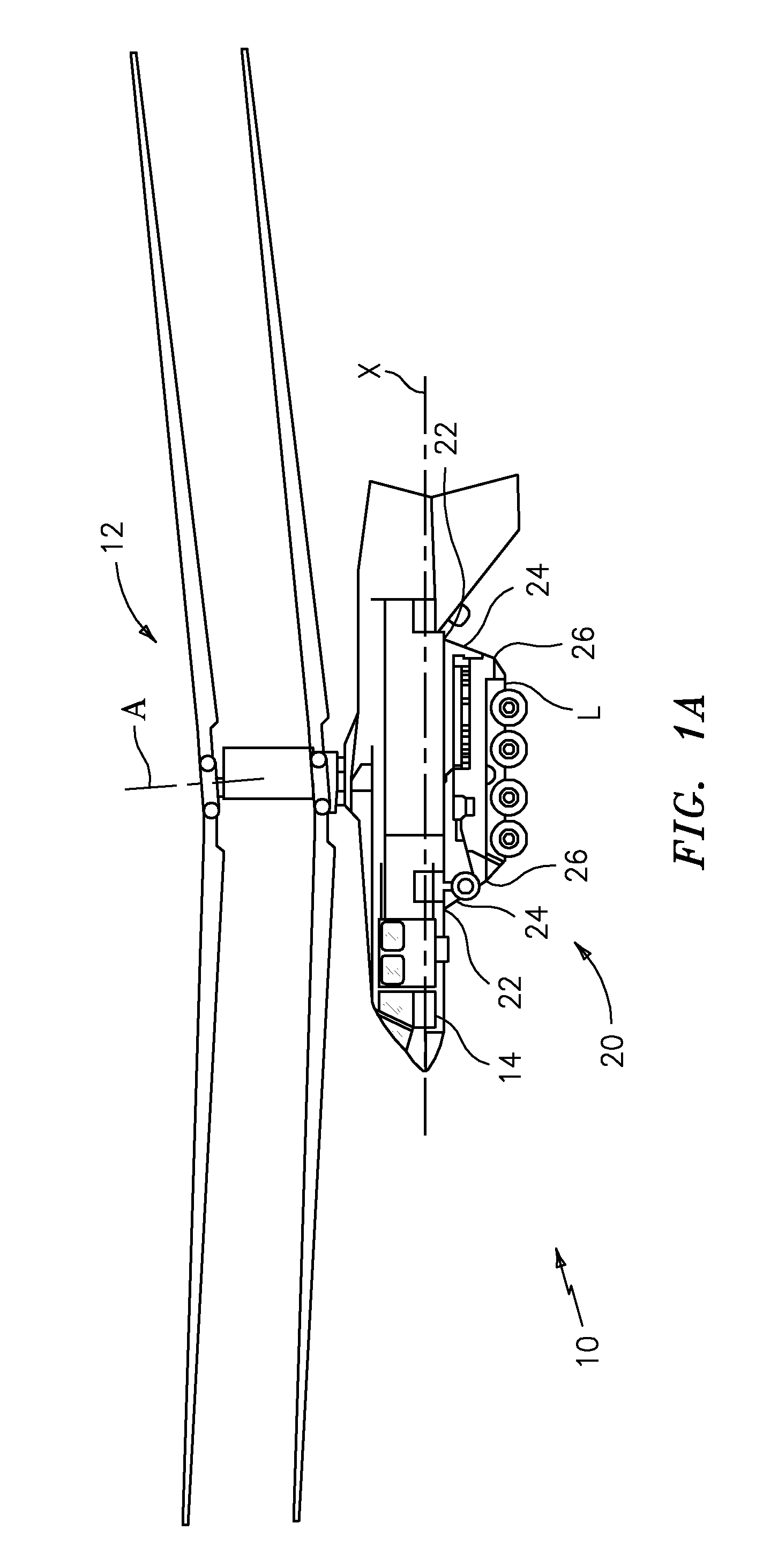
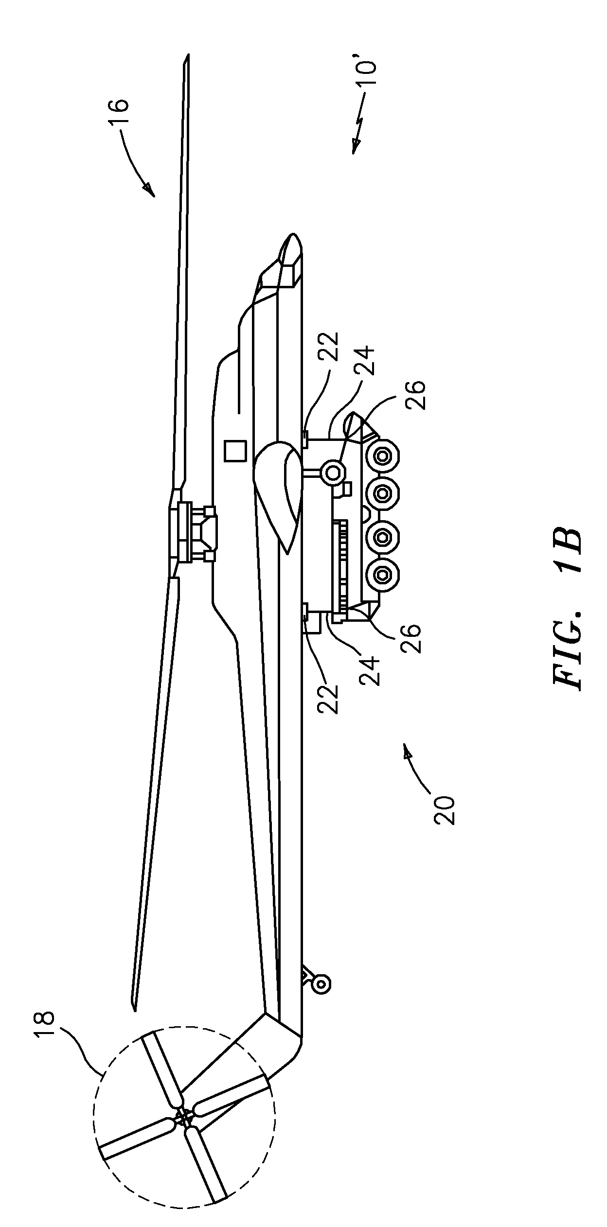
[0033]FIG. 1A schematically illustrates a rotary-wing aircraft 10 having a dual, counter-rotating, coaxial rotor system 12 mounted to an airframe 14. The dual, counter-rotating, coaxial rotor system 12 includes an upper rotor system and a lower rotor system upon an essentially tailless fuselage which facilitates shipboard compatibility. Although a particular type of rotary-wing aircraft configuration is illustrated in the disclosed embodiment, other aircraft such as helicopters 10′ having a single main rotor assembly 16 and an anti-torque rotor 18 (FIG. 1B), high speed compound rotary wing aircraft with supplemental translational thrust systems, dual contra-rotating, coaxial rotor system aircraft, flying cranes, turbo-props, tilt-rotors and tilt-wing aircraft, will also benefit from the present invention.

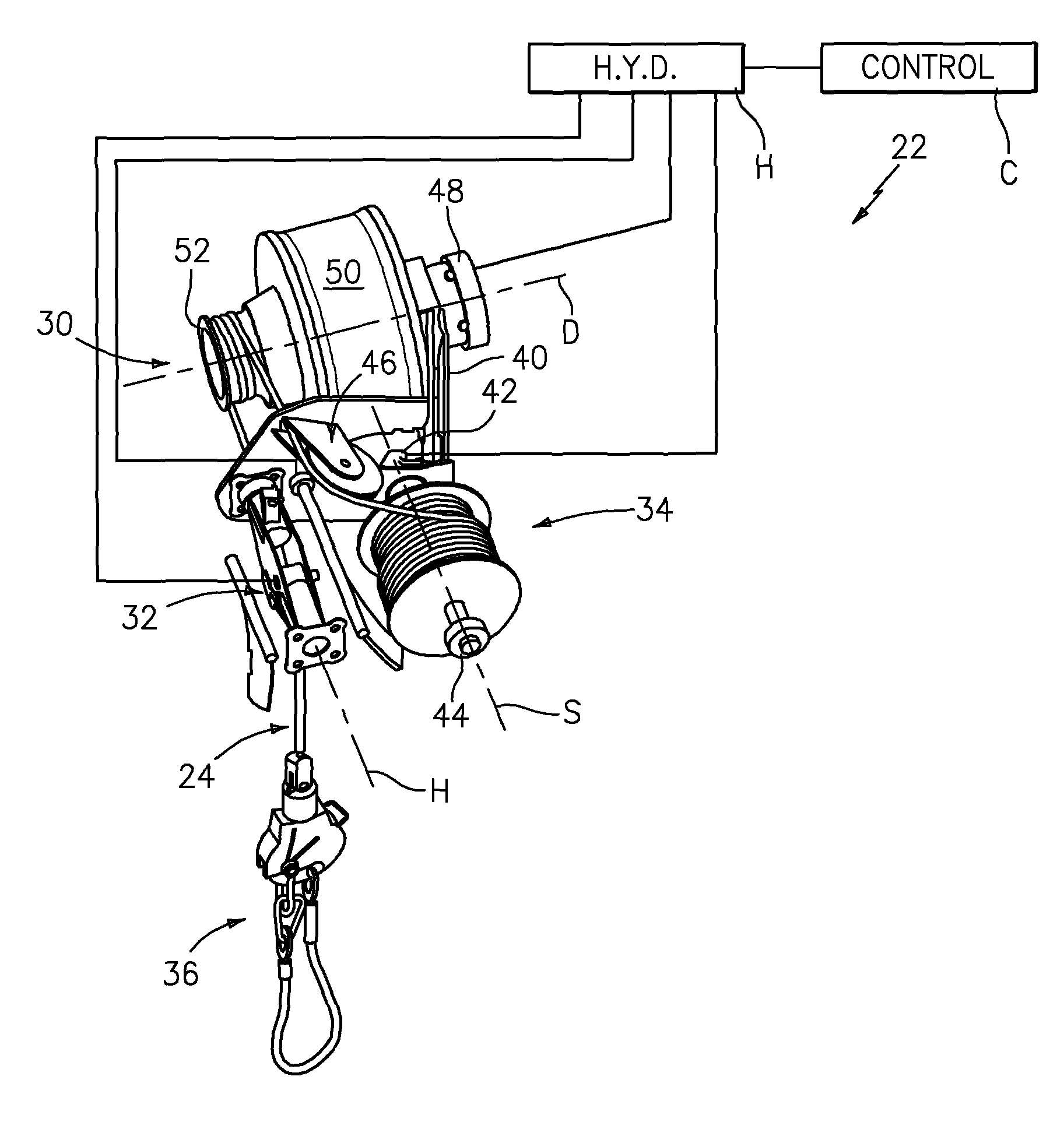
[0034]An external load L is slung from the airframe 14 generally along an aircraft longitudinal axis X through an external cargo hook system 20 having a multitude of winch systems 2...


PUM


Abstract

A winch system includes a cable storage system (34), a drive system (30) and a deployment system to deploy a cable having a hook system attached thereto. A right angle sheave (46) guides the cable between the cable storage system and the drive system. The drive system includes a dual mode transmission that provides high speed capabilities when moderate to no load is being lifted, while also providing high torque for heavy lift operations at low speeds. The deployment system is rated to support a maximum hook load and is mounted to the airframe for pivotable movement about a deployment axis to enable large cable exit angles.

Description

[0001]This invention was made with government support under Contract No.:W911W6-05-2-0007 with the United States Army. The government therefore has certain rights in this invention.BACKGROUND OF THE INVENTION[0002]The present invention relates to external load operations, and more particularly to a winch system for use with Vertical Takeoff and Landing (VTOL) aircraft.[0003]Vertical takeoff and landing (VTOL) aircraft such as, helicopters, co-axial counter rotating aircrafts, tilt-rotors, tilt-wings, etc., are unique in their ability to carry loads externally. Future military forces require enhanced vertical lift capabilities in a compact package. Super heavy lift (SHL) rotary-wing aircraft are generally defined as an aircraft with future payload capacities in the range of over 80,000 pounds of payload over a 400 mile range.[0004]External load operations provide a rapid procedure to load, transport, and unload cargo. Frequently, one or more winch systems having cables with cargo hoo...

Claims


Application Information

Patent Timeline
Patent Type & Authority Patents(United States)
IPC IPC(8): B66D3/00B65H75/18B66D1/26
CPCB64C27/10B64D1/22B66D1/08B66D1/22B66D1/39B66D1/76
Inventor LAUDER, TIMOTHY F.LOREY, JANIECE M.HARRINGTON, CHRISTOPHER M.
Owner SIKORSKY AIRCRAFT CORP
Why Eureka
Try Eureka