Supercapacitor cover with integrated center terminal

a supercapacitor and center terminal technology, applied in the direction of fixed capacitor details, cell components, cell component details, etc., can solve the problems of difficult to reconcile on the same part, cover, case, etc., to facilitate the contact of the connector and provide sufficient space

Inactive Publication Date: 2011-03-22
BLUE SOLUTIONS
View PDF13 Cites 57 Cited by
  • Summary
  • Abstract
  • Description
  • Claims
  • Application Information

AI Technical Summary

Benefits of technology

[0015]The object of the invention is to facilitate contact of the connector with the sections of the innermost turns of an electric storage component wi

Problems solved by technology

But a supercapacitor generates strong charge or discharge currents on the sections of this collector which is relatively soft, because it is relatively thin, so that a maximum of (surface) sections have to be connected to the terminal or to the cover or to the case, in order to limit the resulting electric connection resistance and therefore heat build-up, notably at the interface between the sections of the collector and the connector.
Moreover, it is difficult to reconcile on a same part (cover, case), a current-collecting central terminal as wide as possible, and a weld in bosses attaining the turns of the centre of the winding, as much as possible.
Indeed, a central terminal should be as superficial as possible (sufficient sectional area for collecting current and letting it flow through) and it therefore occupies a certain surface area at the centre of the cover which may limit accessibility to the bosses and prevent laser shots from reaching the turns of the centre.
From an electrical point of view, this connection generates an additional series resistance detrimental to the properties of the supercapacitor, a process step and therefore a cost, and also additional mechanical brittleness.
The terminals added to the cover or the case by a laser weld, are thus found to have brittleness of the connection between both parts.
Jamming two cones with each other for attaching the terminal is of course suggested, but such jamming increases heat build-ups by the surface contact resistance at the interface between both mutually jammed parts.
Moreover, fitting of the parts should then be perfect, which generates significant machining costs.

Method used


Image

  • Supercapacitor cover with integrated center terminal
  • Supercapacitor cover with integrated center terminal
  • Supercapacitor cover with integrated center terminal

Examples


Embodiment Construction

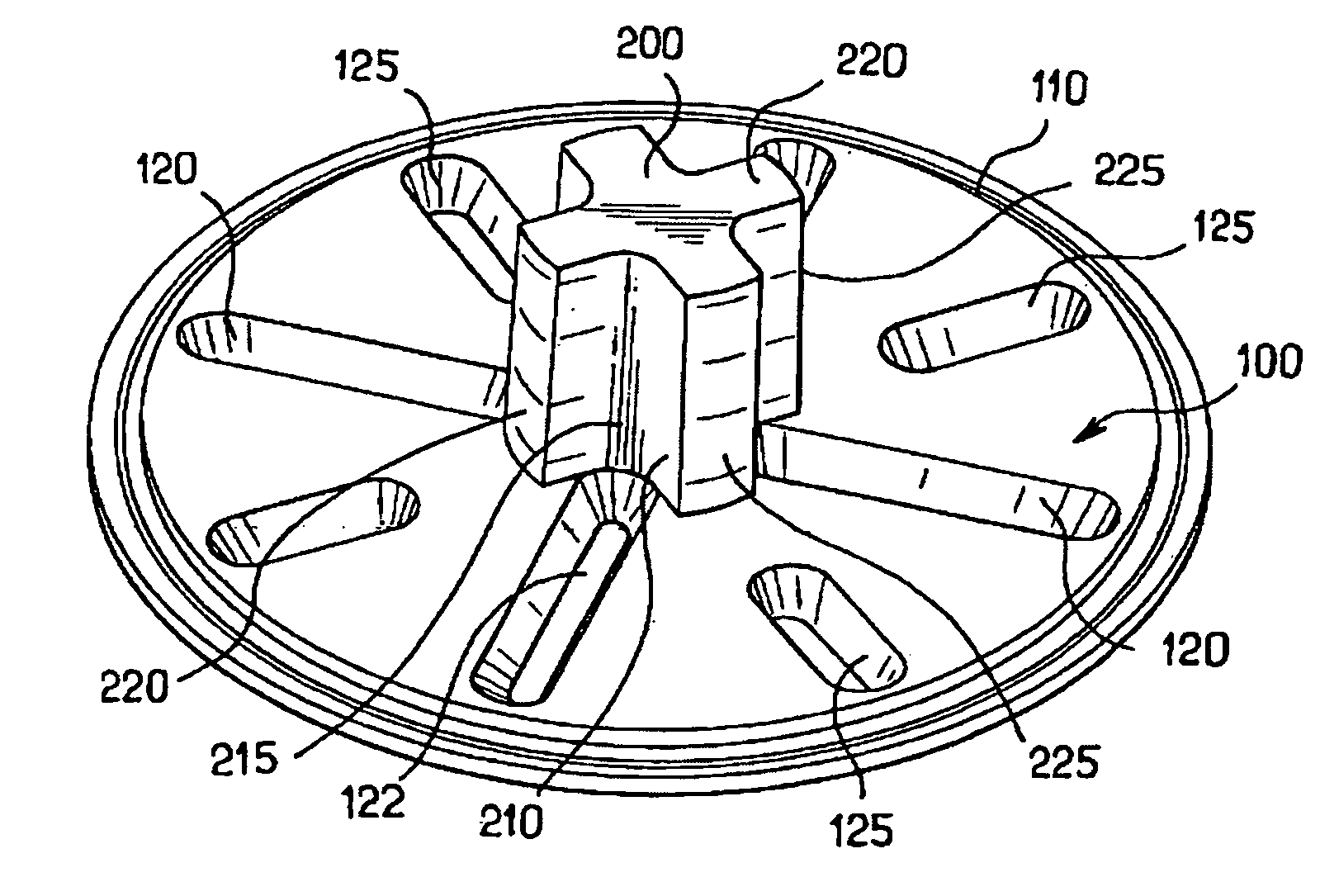
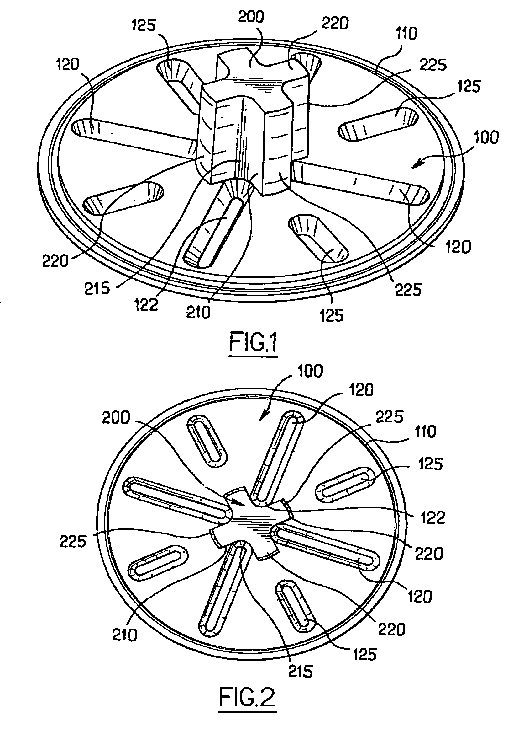
[0035]The connector of FIG. 1 is a one-piece part, here in aluminium, including both a plate 100 intended for covering and contacting turns of a supercapacitor winding, and an upper trunnion 200 rising in the central portion of this plate in order to form the outer connection terminal of a supercapacitor.

[0036]The cover plate is a disk with a contour substantially matching that of the winding to be covered, this contour being provided here with a groove 110 intended for receiving a gasket for sealing the supercapacitor.

[0037]This plate has a series of deformations or bosses 120, 125 which rise and form a relief on a lower face of the plate 100, i.e., on the face opposite to the one where the external connection terminal 200 rises.

[0038]These bosses have a small height relatively to that of the terminal 200 but most of them have sufficient extent in order to radially cross a majority of the turns of the winding.

[0039]In order to contact a maximum of these sections, the bosses 120, 12...


PUM


Abstract

An electric energy storage component having coil windings and at least one connector. A plate of the connector is in contact with the coil windings. The plate of the connector has a surface which is provided with a terminal wherein the shape thereof is essentially that of a revolution. The plate also forms a series of bosses extending in a raised manner along a surface of the plate opposite to that containing the terminal. The terminal has at least one inner recess and at least one boss which penetrates into the recess.

Description

[0001]The present patent application is a non-provisional application of International Application No. PCT / FR2005 / 001425, filed Jun. 9, 2005.BACKGROUND OF THE INVENTION[0002]1. Field of the Invention[0003]The invention relates to electrical connection and external casing arrangements for electric energy storage components (batteries, capacitors, for example capacitors of the electrochemical type) and notably for supercapacitors.[0004]2. Description of Related Art[0005]An electric energy storage component, notably a supercapacitor, appears as a winding of several material layers with, jutting out from each end of the winding, a sheet based on aluminium, called a collector, and which enables the current to be drained outwards. This collector should be electrically connected to an electric connection terminal which is part of the global supercapacitor casing, either in its cover, or in its case.[0006]Welding the collector onto the connector of the terminal by a weld is known, possibly ...

Claims


Application Information

Patent Timeline
IPC IPC(8): H01G9/00H01G4/32H01G9/008H01G9/155H01M50/147H01M50/682
CPCH01G4/32H01G9/008H01G9/155H01M2/26H01M2/04Y02E60/13H01M2/36Y02E60/10H01M50/147H01G11/78H01G11/82H01G11/76H01M50/682H01G4/228
Inventor CAUMONT, OLIVIERHASCOET, XAVIER
Owner BLUE SOLUTIONS
Why Eureka
Try Eureka