Thermal variable resistance device with protective sheath

a technology of variable resistance and protective sheath, which is applied in the direction of thermometer details, instruments, heat measurement, etc., can solve the problems of material damage, substantial mechanical strength decline, and current temperature sensors limited to an operating envelop

Inactive Publication Date: 2011-03-29
GOLDMAN SACHS BANK USA AS SUCCESSOR COLLATERAL AGENT +1
View PDF41 Cites 3 Cited by
  • Summary
  • Abstract
  • Description
  • Claims
  • Application Information

AI Technical Summary

Benefits of technology

[0021]Accordingly, it is an object of the present invention to provide sensor with a rugged sheath exhibiting high mechanical hardness for protection of the sensor and / or conductors connected thereto.
[0022]Accordingly, it is another object of the present invention to provide an extended temperature range thermal variable resistance device with enhanced high temperature operating characteristics and long term, stable output and minimum drift in resistance.
[0025]Yet another object of the present invention is to provide a method for the production of a cost effective, high reliability, stable resistance device with an operating range of up to 1700° C. (3092° F.) in hostile environments.
[0027]It is contemplated that virtually any standard thermal resistive device may effectively be utilized in connection with the sheath comprising the above-described sheath material.

Problems solved by technology

These materials suffer from the detrimental effects of contamination, ionic migration, sublimation, oxidation and substantial decrease in mechanical strength with increased operating temperatures.
Current temperature sensors are thus limited to an operating envelope of less than 650° C.
(1562° F.) but are either limited to specific environmental conditions (such as for instance: a vacuum environment, an inert gas environment, or a hydrogen atmosphere) and / or must be limited to short term operation to prevent premature failure.
This temperature operating range has limited the application of these sensors in hostile, high temperature systems such as those commonly encountered in the aerospace, petroleum and glass industries.
Even though the temperature measurement conducted by employing a RTD is well known in the art, broad application of the RTD is still limited in high temperature hostile environments.
Prior art temperature sensors have had the disadvantage of melting at fairly low temperature and have required insulation and various sheathing systems to protect the sensor during operation at prolonged elevated temperatures.
However, this sometimes results in undesirable reactions between the metals in the temperature sensor and the materials used in the insulation and sheathing systems.
The insulation and sheathing systems have the further disadvantage of resulting in time delays in obtaining temperature readings due to the insulation and mechanical packaging designed to prevent failure resulting from such problems as gas leakage at the RTD sheath seals, cracked sheaths and other mechanical limitations imposed by ceramic insulated metal sheathed sensors.
Such metals, however, are not widely used because they are more susceptible to oxidation than platinum, and degrade by drift caused by selective oxidation.
However, problems can occur after alloying.
For example, when a high concentration of any alloying element is added to the platinum base, the electrical properties of the resulting platinum limb become inferior; at the same time the hardening phase will partially or totally dissolve into the base at high temperatures, thus the effects of the hardening action are reduced.
The prior art attempts to extend the operation range of variable-resistance temperature device have been limited to extending the range of known resistant materials through the use of insulation techniques or increasing the high temperature properties of known materials through alloying processes or coatings.
The disadvantages of these techniques, including not reaching a high enough operating temperature, are discussed above.
Dispersion hardened materials contain finely distributed transition element oxide particles which suppress grain growth and recrystallization even at the highest temperatures and also hinder both the movement of dislocations and sliding at the grain boundaries.

Method used


Image

  • Thermal variable resistance device with protective sheath
  • Thermal variable resistance device with protective sheath
  • Thermal variable resistance device with protective sheath

Examples


Embodiment Construction

[0049]Referring now to the drawings, wherein like reference numerals designate corresponding structure throughout the views.

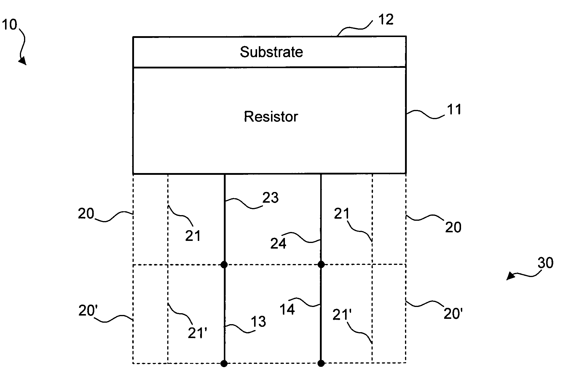
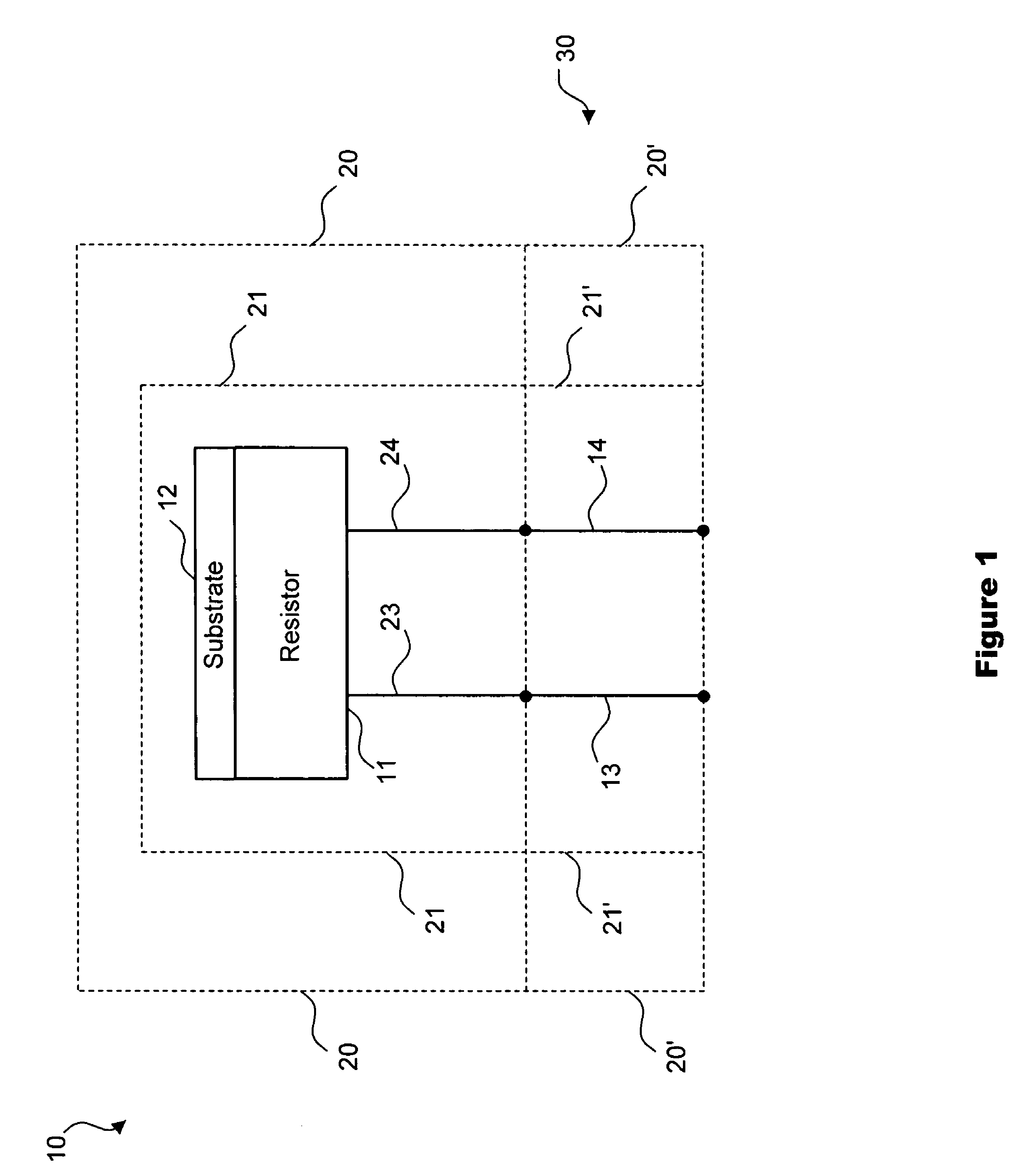
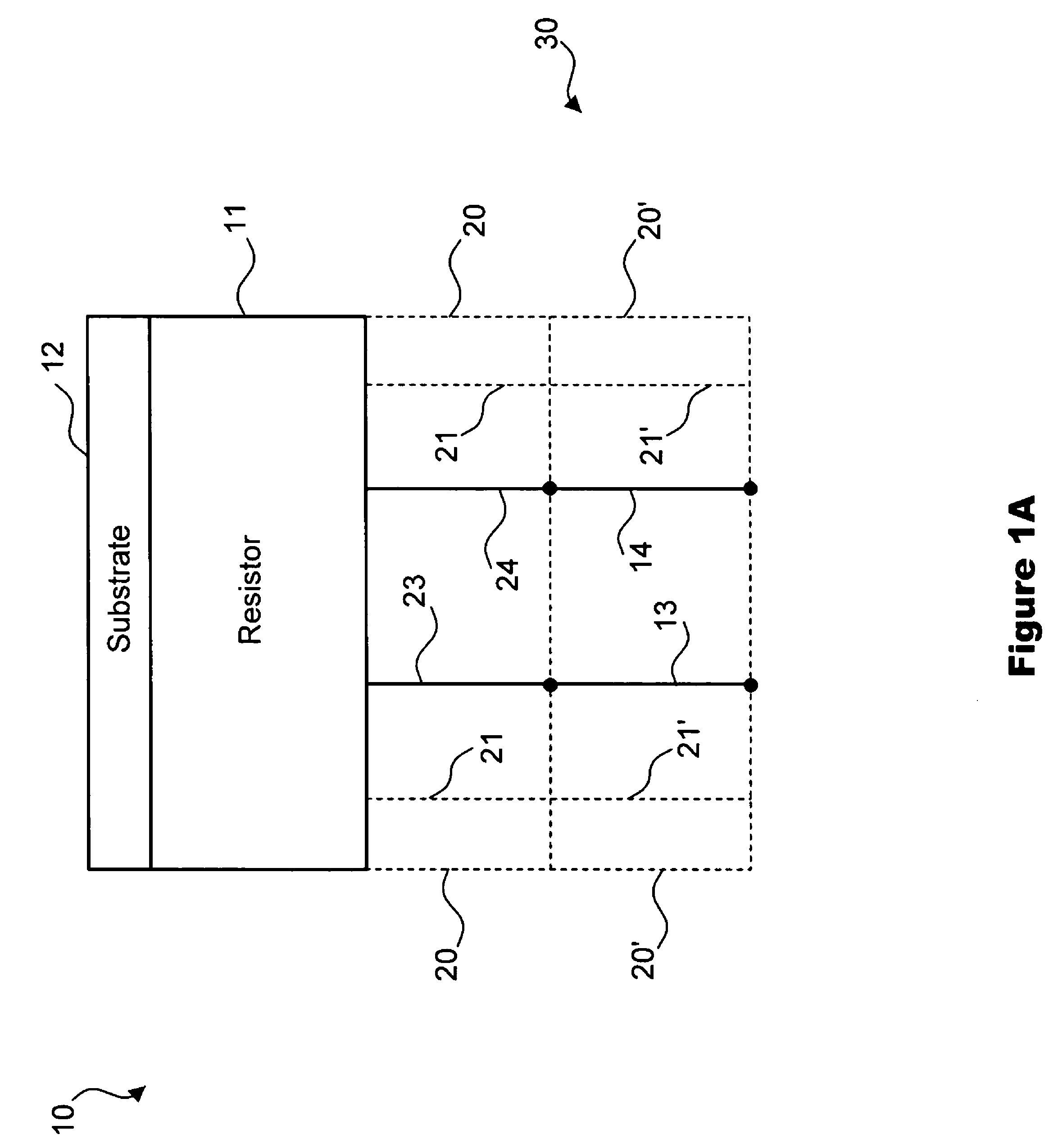
[0050]FIG. 1 is a block diagram illustrating one preferred embodiment of the present invention showing sensor 10. A substrate 12 is shown in contact with a resistor 11. Also shown are first conductor 23 and second conductor 24 electrical both of which are shown connected to resistor 11.

[0051]Sensor 10 is further illustrated in FIG. 1 with insulation 21. The insulation may comprise any suitable insulating material desired including but not limited to a refractory ceramic material such as for instance, Al2O3 or MgO. Although insulation 21 is shown in FIG. 1 enclosing sensor 10, it is contemplated that insulation 21 may only enclose a portion of sensor 10, such as for instance, first and second conductors 23, 24 or resistor 11, or any other portion thereof.

[0052]Also illustrated in FIG. 1 is sheath 20 shown enclosing insulation 21. Sheath 20 may comprise, for inst...


PUM

PropertyMeasurementUnit
temperaturesaaaaaaaaaa
temperatureaaaaaaaaaa
resistance temperatureaaaaaaaaaa

Abstract

A sensor and method of manufacturing a variable resistance sensor with a protective sheath that is cost effective and highly reliable, with stable resistance with an operating range of up to 1700° C. in hostile environments. The sheath is formed of highly stable dispersion hardened materials capable of withstanding mechanical loads and chemical attacks at elevated temperatures while maintaining internal chemical integrity.

Description

CROSS-REFERENCE[0001]This application is a continuation in part of and claims the benefit of the filing date of U.S. patent application Ser. No. 10 / 712,484 filed Nov. 13, 2003 now U.S. Pat. No. 7,026,908.FIELD OF THE INVENTION[0002]The present invention relates to a device of which an electrical resistance will change in response to a change in surrounding temperature, and more specifically to the construction of a sheath formed of a material exhibiting high mechanical strength for protecting the device from physical damage.BACKGROUND OF THE INVENTION[0003]Conventional resistance temperature detectors (RTD), use a variety of materials to produce elements with high operating temperatures. These materials suffer from the detrimental effects of contamination, ionic migration, sublimation, oxidation and substantial decrease in mechanical strength with increased operating temperatures. Current temperature sensors are thus limited to an operating envelope of less than 650° C. (1200° F.) t...

Claims


Application Information

Patent Timeline
Patent Type & Authority Patents(United States)
IPC IPC(8): H01C7/10G01K1/10G01K1/12G01K7/18
CPCG01K1/10G01K1/12G01K7/18
Inventor HABBOOSH, SAMIR W.
Owner GOLDMAN SACHS BANK USA AS SUCCESSOR COLLATERAL AGENT
Why Eureka
Try Eureka