

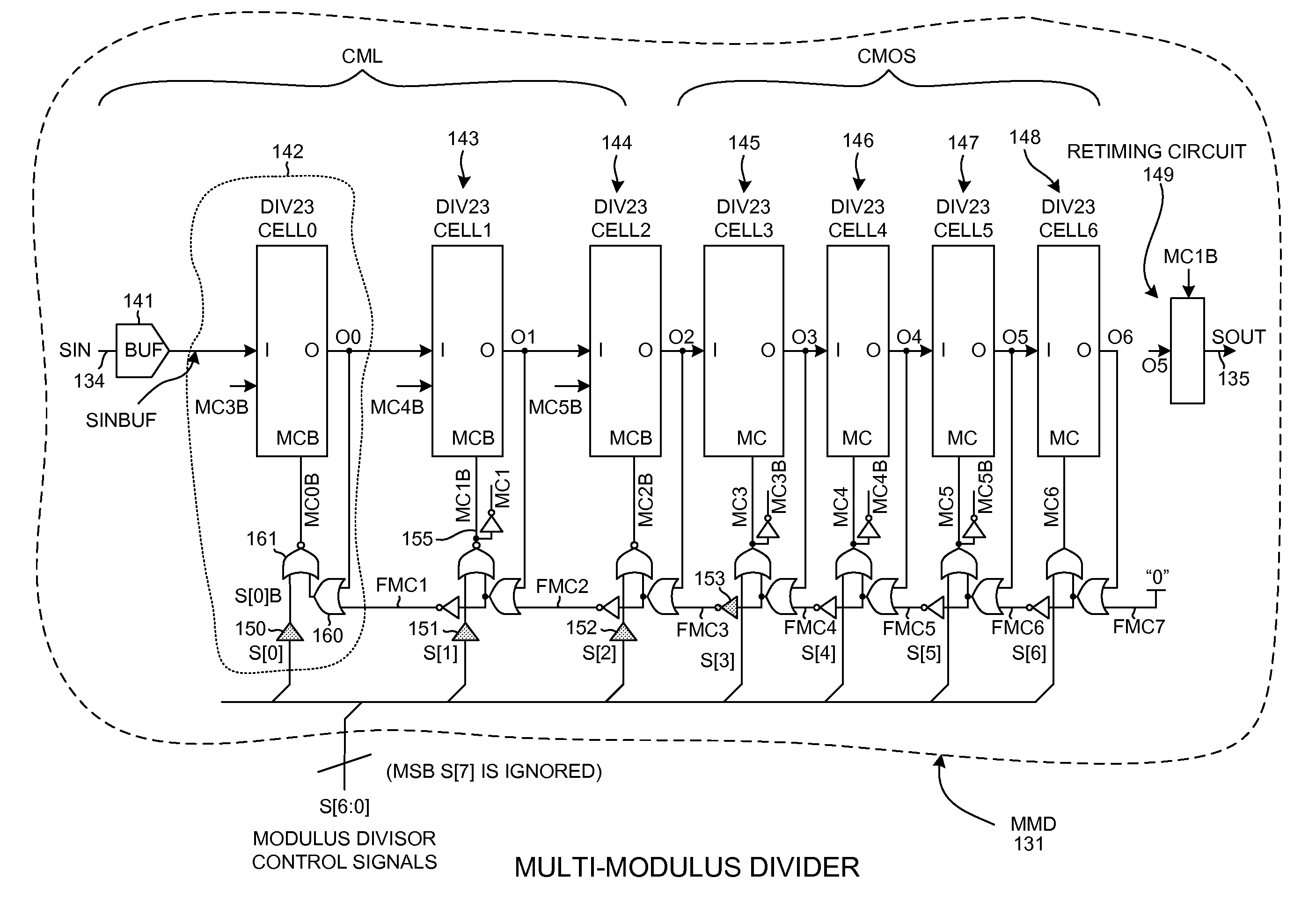
Multi-modulus divider retiming circuit
a multi-modulus divider and retiming circuit technology, applied in the field of multi-modulus dividers, can solve the problems of unable to meet the noise requirement imposed on the mmd by the cellular telephone standard, difficult to maintain an adequate constant phase relationship between the two signals, and accumulated jitter
- Summary
- Abstract
- Description
- Claims
- Application Information
AI Technical Summary
Benefits of technology
Problems solved by technology
Method used
Image

Examples
Embodiment Construction
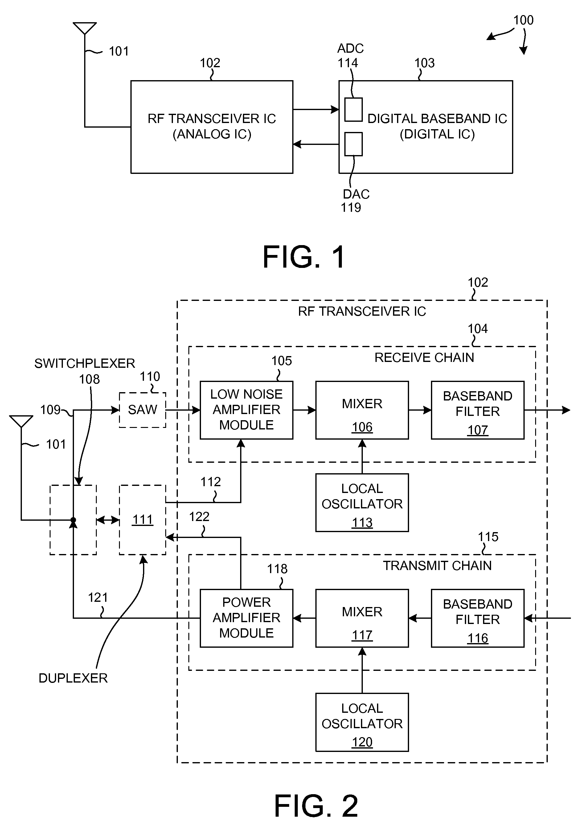
[0027]FIG. 1 is a simplified diagram of a mobile communication device 100 in accordance with one novel aspect. Mobile communication device 100 in this case is a cellular telephone. Cellular telephone 100 includes an antenna 101 and several integrated circuits including a novel radio frequency (RF) transceiver integrated circuit 102 and a digital baseband integrated circuit 103. Digital baseband integrated circuit 103 includes primarily digital circuitry and includes a digital processor. An example of digital baseband integrated circuit 103 is the MSM6280 available from Qualcomm Inc. Novel RF transceiver integrated circuit 102 includes circuits for processing analog signals.
[0028]FIG. 2 is a more detailed diagram of the RF transceiver integrated circuit 102 of FIG. 1. The receiver “signal chain”104 includes a low noise amplifier (LNA) module 105, a mixer 106, and a baseband filter 107. When receiving in a GSM (Global System for Mobile Communications) mode, a signal on antenna 101 pas...
PUM
 Abstract
Description
Claims
Application Information