Time varying voltage combustion control and diagnostics sensor

a technology of diagnostic sensor and time-varying voltage, which is applied in process control, lighting and heating apparatus, instruments, etc., can solve problems such as unplanned shutdown, reduced component life, and flame instability of advanced combustors, and achieve the effect of reducing flame instability and pollutant emissions

Inactive Publication Date: 2011-04-19
THE UNITED STATES AS REPRESENTED BY THE DEPARTMENT OF ENERGY
View PDF40 Cites 38 Cited by
  • Summary
  • Abstract
  • Description
  • Claims
  • Application Information

AI Technical Summary

Benefits of technology

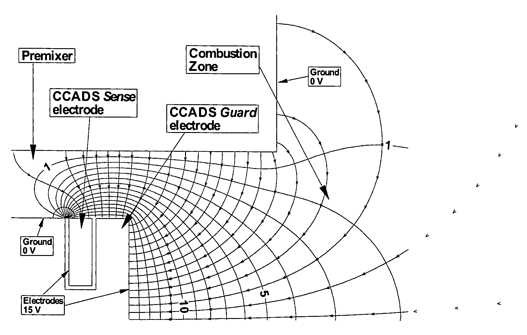
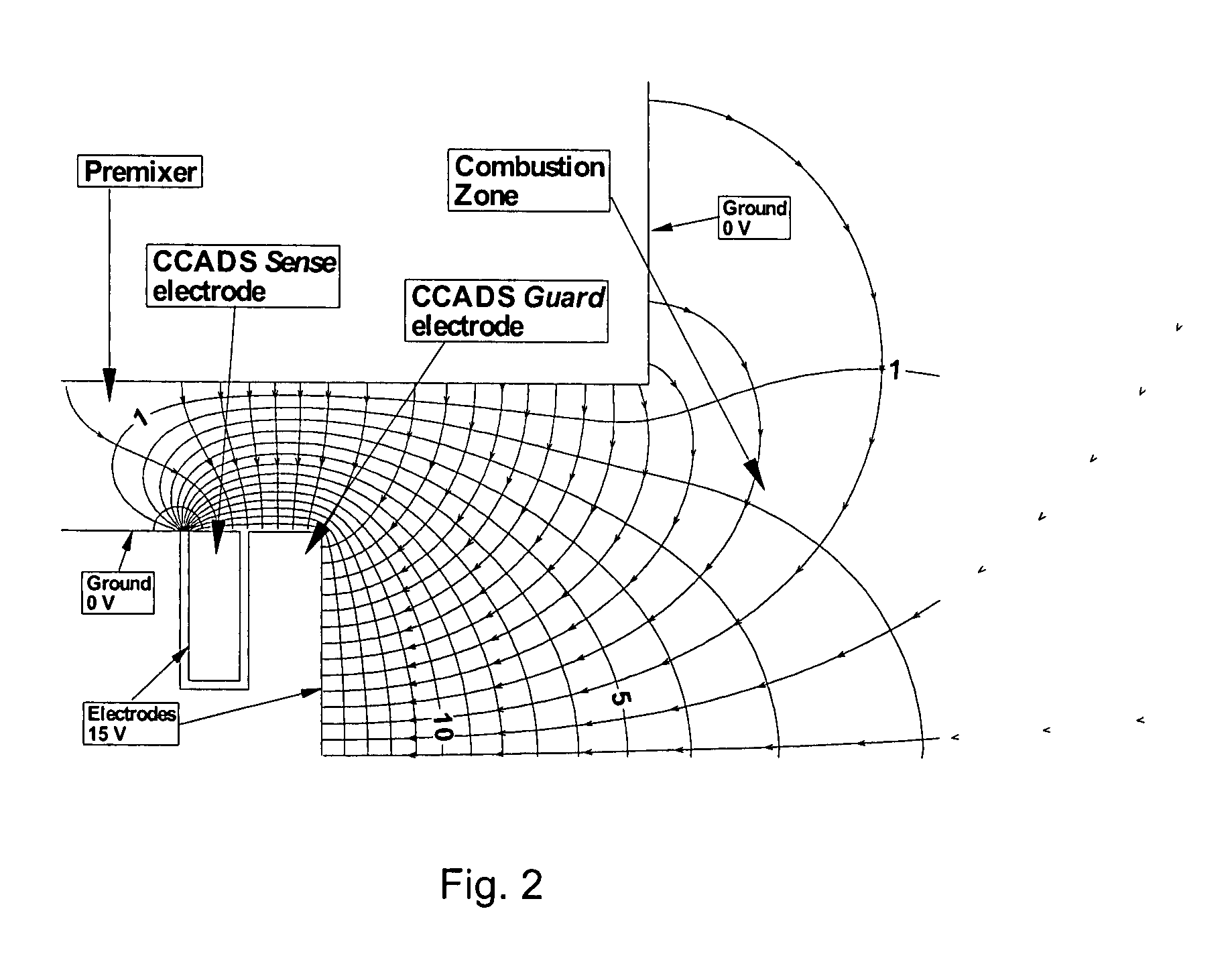
[0012]An embodiment of the invention is directed to a method and system for the real-time monitoring and control of a combustion process in the combustion zone of a combustion chamber, wherein a fuel/oxidant mixture characterized by a fuel/oxidant ratio is directed into the combustion zone via a fuel/oxidant inlet and is ignited for maintaining a combustion flame in the combustion zone, the method comprising the steps of providing a sensor having a first electrode disposed adjacent the combustion zone and an electrical ground, wherein the combustion flame is disposed a distance d from the first electrode; applying a time-varying alternating voltage to the first electrode and measuring an alternating electric current in the combustion flame between the first electrode and ground, wherein the current varies with the position of the flame from the first electrode within the combustion

Problems solved by technology

Although capable of producing ultra-low emissions (<10 ppm NOx), these advanced combustors suffer from flame instability problems such as flashback, combustion dynamics, and lean blowout.
These problems cause reduced component life, unplanned shutdowns, and potentially catastrophic engine

Method used


Image

  • Time varying voltage combustion control and diagnostics sensor
  • Time varying voltage combustion control and diagnostics sensor
  • Time varying voltage combustion control and diagnostics sensor

Examples


Embodiment Construction

[0026]The operating equivalence ratio (φ) for a combustor using air as the oxidant is defined as

[0027]Φ=(Fuel / Air)(Fuel / Air)stoichiometric(1)

[0028]Flame current measurements have been successfully correlated with the hydrocarbon concentrations in a number of applications. Most notable is the flame ionization detector (FID) used in gas chromatographs, where the relationship of current to hydrocarbon concentration is generally determined by

i=r[CnHm]Q  (2)

where r is the charge per mole of hydrocarbon, [CnHm] is the molar concentration of the hydrocarbons, and Q is the volumetric flow rate. The linearity of the FID measurements depends on the consistency of charge collection. This is accomplished by providing consistent inlet bulk flow velocity, a constant electric field across the flame, and using a hydrogen flame to ignite the inlet sample and maintain a stable flame.

[0029]Successful demonstrations of a flame ionization sensor for measuring the local fuel / air ratio in an internal comb...


PUM


Abstract

A time-varying voltage is applied to an electrode, or a pair of electrodes, of a sensor installed in a fuel nozzle disposed adjacent the combustion zone of a continuous combustion system, such as of the gas turbine engine type. The time-varying voltage induces a time-varying current in the flame which is measured and used to determine flame capacitance using AC electrical circuit analysis. Flame capacitance is used to accurately determine the position of the flame from the sensor and the fuel/air ratio. The fuel and/or air flow rate (s) is/are then adjusted to provide reduced flame instability problems such as flashback, combustion dynamics and lean blowout, as well as reduced emissions. The time-varying voltage may be an alternating voltage and the time-varying current may be an alternating current.

Description

STATEMENT REGARDING FEDERALLY SPONSORED RESEARCH OR DEVELOPMENT[0001]The United States Government has rights in this invention pursuant to the employer-employee relationship of the U.S. Department of Energy and the inventors.FIELD OF THE INVENTION[0002]This invention relates generally to the monitoring and control of an industrial combustion process, and is particularly directed to an improved sensor arrangement and method for monitoring and diagnosis of the combustion process in a lean-premix gas turbine combustor to allow for the exercise of real-time control over the combustion process.BACKGROUND OF THE INVENTION[0003]The requirement to reduce pollutant emissions has motivated turbine manufacturers to develop advanced combustion technologies. Although capable of producing ultra-low emissions (<10 ppm NOx), these advanced combustors suffer from flame instability problems such as flashback, combustion dynamics, and lean blowout. These problems cause reduced component life, unpla...

Claims


Application Information

Patent Timeline
IPC IPC(8): F23N5/00
CPCF23N1/022F23N5/242F23N2023/42F23N2029/00F05D2270/083F23R2900/00013F05B2270/1062F05B2270/1063F05D2270/082F23N2041/20F23N2223/42F23N2229/00F23N2241/20
Inventor CHORPENING, BENJAMIN T.THORNTON, JIMMY D.HUCKABY, E. DAVIDFINCHAM, WILLIAM
Owner THE UNITED STATES AS REPRESENTED BY THE DEPARTMENT OF ENERGY
Why Eureka
Try Eureka