
Method and apparatus for prevention of catheter air intake

a catheter and air intake technology, applied in the field of cardiology, radiology, electrophysiology or endovascular surgery, can solve the problems of air embolism, air embolism traversing from the right heart to the left heart during right heart interventional procedures, and potential negative pressure gradient between the rooms

Inactive Publication Date: 2011-05-03
INDIAN WELLS MEDICAL
View PDF16 Cites 55 Cited by
  • Summary
  • Abstract
  • Description
  • Claims
  • Application Information

AI Technical Summary

Benefits of technology

Effectively prevents air embolisms by actively removing air bubbles and gas from the catheter or sheath, ensuring air-free liquid is returned to the patient's system, reducing the risk of catastrophic outcomes during cardiovascular procedures.

Problems solved by technology

Such gradients in the presence of a Patent Foramen Ovale (PFO), a not uncommon congenital cardiac condition, can easily result in air emboli traversing from the right heart to the left heart during right heart interventional procedures.
In addition, these relatively low pressures can exist for a non-trivial portion of the cardiac cycle resulting in the potential for a negative pressure gradient between the room pressure, which in a clean room, catheterization lab, or surgical suite is generally slightly elevated, and the distal end of the introduction sheath.
There is a potential for any gas or air entrained into the proximal end of the introduction sheath to migrate out the distal end of the introduction sheath and into the patient's cardiovascular system where it could cause an air embolism.
The clinical ramifications of an air embolism range from no noticeable effect to cerebrovascular stroke or cardiac ischemia, either of which could have mild to severe outcomes and could even result in patient death.
Thus, any air that inadvertently enters the sheath or catheter system is at risk for introduction to the patient, an event with potentially catastrophic consequences such as cerebrovascular embolism, coronary embolism, and the like.
Air embolism is clearly an issue especially with catheters directed toward the cerebrovasculature or the coronary circulation, but also with catheters or sheaths directed anywhere within the circulatory system of the mammalian patient.

Method used


Image

  • Method and apparatus for prevention of catheter air intake
  • Method and apparatus for prevention of catheter air intake
  • Method and apparatus for prevention of catheter air intake

Examples


Embodiment Construction

[0034]As used herein the terms distal and proximal are used to clarify the location of various points along the axial length of a catheter or sheath. Points are defined with respect to the end grasped by the user and the end that is inserted in the patient in the same manner as would one skilled in the art of medical device catheter construction. The proximal end of the catheter or sheath is defined as that end closest to the user or operator, or user, of the catheter or sheath while the distal end of the catheter or sheath is defined as that end that is inserted into the patient.

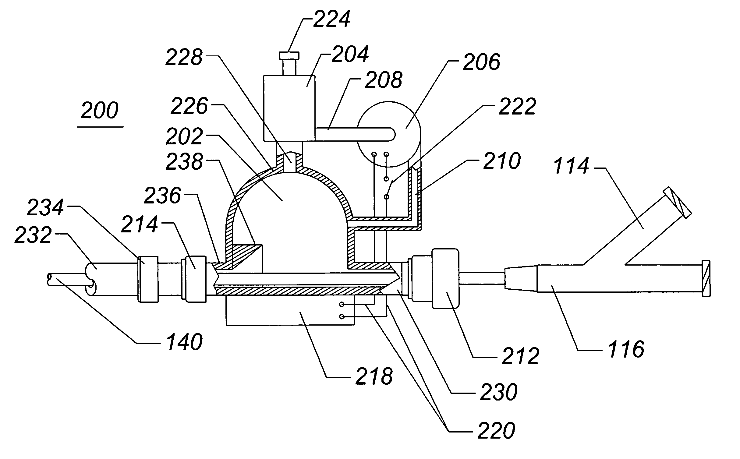
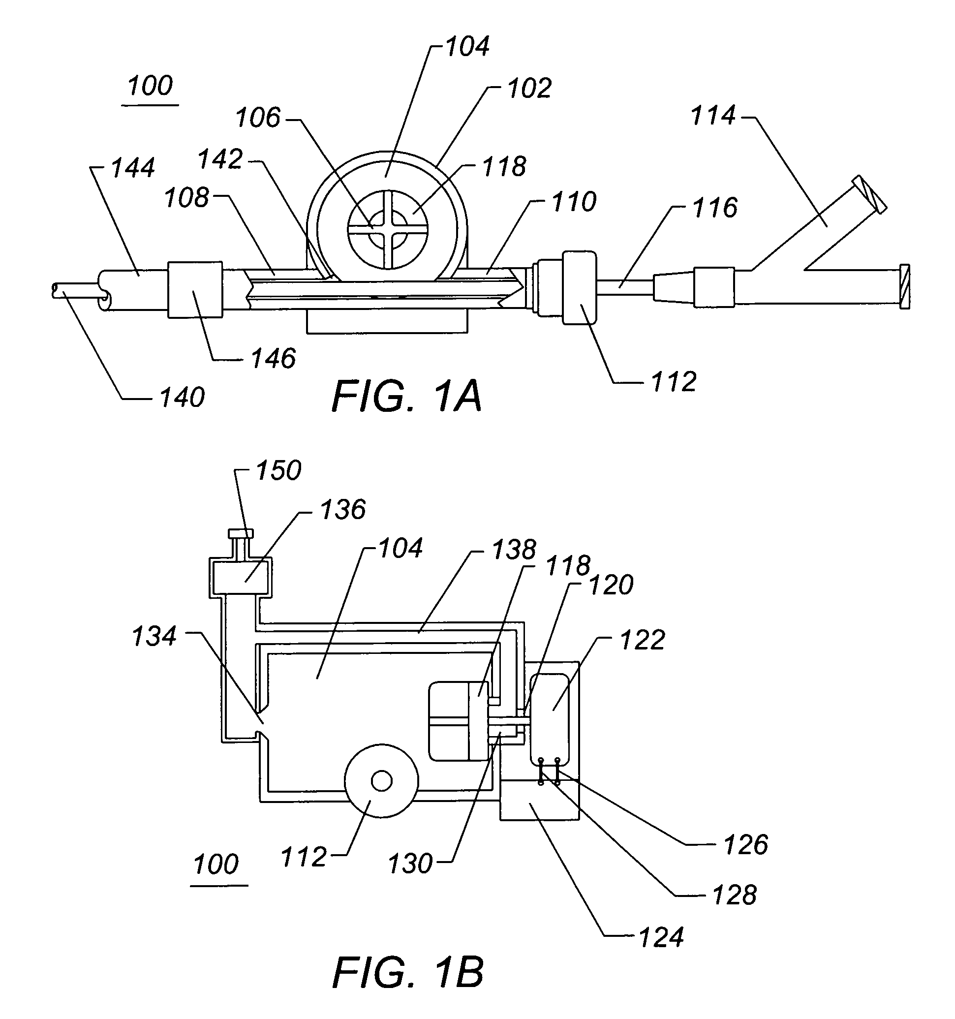
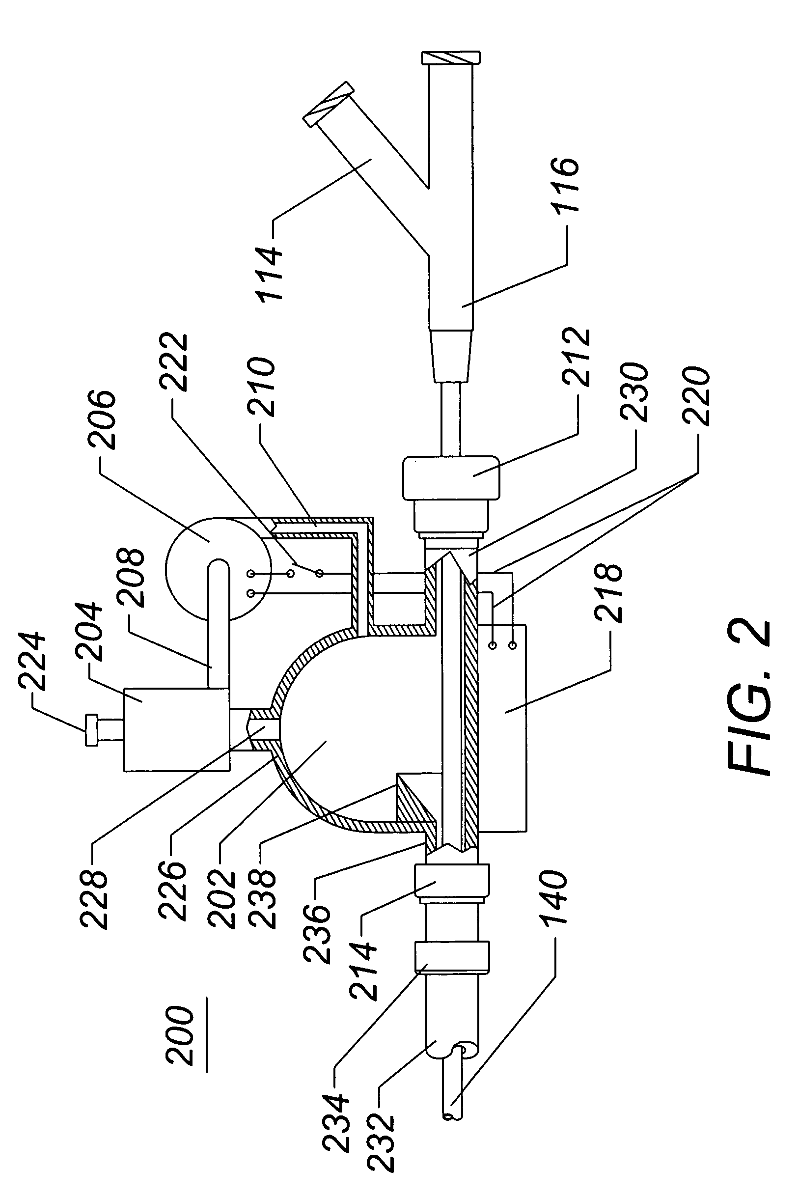
[0035]FIG. 1A illustrates a side view of a catheter blood air filter assembly 100 of the present invention. The filter assembly 100 comprises a shell 102 further comprising an internal chamber 104, and an impeller 118 further comprising a plurality of vanes 106. The filter assembly 100 further comprises a second catheter inlet port 110, a second catheter outlet port 108, an inlet hemostasis valve 112, an op...


PUM


Abstract

A system for preventing air from entering a first catheter of a multi-catheter system. Air is prevented from entering the proximal end of the first catheter by an axially elongate chamber having an impeller, the chamber being affixed to the proximal end of the first catheter. The air is removed through a port near the centerline of the chamber. Liquid removed with the air is returned to the chamber to minimize liquid loss during the procedure. A second catheter inserted through the chamber and into the first catheter is unable to entrain gas into the first catheter because any gas that enters the chamber is routed to the centerline of the chamber where it is removed. Inflow of fluid from an external pump scrubs the second catheter shaft of air bubbles attached by surface tension.

Description

PRIORITY CLAIM[0001]This application claims priority benefit under 35 USC §119(e) from U.S. Provisional Application No. 61 / 008,952, filed Dec. 21, 2007, entitled METHOD AND APPARATUS FOR PREVENTION OF CATHETER AIR INTAKE, and U.S. Provisional Application No. 61 / 069,979, filed Mar. 19, 2008, entitled METHOD AND APPARATUS FOR PREVENTION OF CATHETER AIR INTAKE the entire contents of both of which are hereby incorporated herein by reference.FIELD OF THE INVENTION[0002]The field of this invention is cardiology, radiology, electrophysiology, or endovascular surgery, and more particularly the fields of cardiac or circulatory system catheterization.BACKGROUND OF THE INVENTION[0003]Catheters are introduced into the cardiovascular system for various diagnostic and therapeutic reasons. Catheters are often introduced into the cardiovascular system through introduction sheaths that provide a pre-determined conduit from the access site to the treatment site and facilitate vascular access of new c...

Claims


Application Information

Patent Timeline
Patent Type & Authority Patents(United States)
IPC IPC(8): A61M31/00A61M1/00
CPCA61M5/36
Inventor BREZNOCK, EUGENE M.LENKER, JAY A.WIETING, DAVID W.
Owner INDIAN WELLS MEDICAL
Learn More