Three degree of freedom parallel mechanism, multi-axis control machine tool using the mechanism and control method for the mechanism

a technology of multi-axis control and parallel mechanism, which is applied in the direction of mechanical control devices, process and machine control, instruments, etc., can solve the problems of inability to compensate, deformation of jointing rods, errors in positioning, etc., and achieve excellent responsiveness (quick response capability) in control, the effect of improving the accuracy of positioning control

Inactive Publication Date: 2011-05-10
JTEKT CORP
View PDF15 Cites 20 Cited by
  • Summary
  • Abstract
  • Description
  • Claims
  • Application Information

AI Technical Summary

Benefits of technology

It is therefore a primary object of the present invention to provide an improved three degree of freedom parallel mechanism which is simple in construction, is essentially high in rigidity, is wide in the movable range for a movable body (spindle head) to turn angularly, and is essentially high in absolute accuracy in positioning.
Another object of the present invention is to provide an improved three degree of freedom parallel mechanism which is easy to calibrate kinematic parameters and is also easy to enhance the controllability (responsiveness) in feedback control.
A further object of the present invention is to provide an improved control method and device for a three degree of freedom parallel mechanism, capable of obviating errors in machining parts constituting the mechanism and errors due to the thermal deformation of the parts so that the parallel mechanism can be enhanced in positioning accuracy and can be improved in the controllability (responsiveness) in positioning control.
With the construction in the first aspect, respective one ends of the rods are jointed to output ends of the actuators, while respective other ends of the rods are jointed to the movable body. Thus, each of the rod-like members has stretch and compression forces acting thereon, but does not suffer from any bending stress, so that the parallel mechanism can advantageously be enhanced in mechanical rigidity. Further, since directly jointed to the movable body are only three rod-like members, there can be realized an advantage that the movable body such as, e.g., a tool spindle head, can have a wider range of pivotal movement without suffering from the interference with the linear guides. Further, since the movable body is carried by a movable body support structure which enables the movable body to be movable along the Z-axis and pivotable along each of the A and B-axes, the movements of the movable body along each axis can be directly detected by position detectors such as, e.g., encoders, so that position detections can be attained substantially without needs for conversion calculations. This results in further advantages that the absolute accuracy in positioning is essentially high and that the calibration of the kinematic parameters can be done easily.
With the construction in the third aspect, since the kinematic parameter identification step is executed based on the plural sets of inversely converted command positions and the corresponding plural sets of inversely converted actually measured positions, the kinematic parameters can be identified to take into account not only design values but also errors involved in machining the components for the parallel mechanism. In addition, since the kinematic parameters are compensated or calibrated based on the inversely converted command positions and the corresponding inversely converted actually measured positions which are obtained at every moment, the control is executed in dependence on the present kinematic parameters which are accurate to cope with the thermal deformation of the mechanism components, so that the positioning can be done precisely. Moreover, since feedback control is executed on the basis of the positions which have been calculated by the use of more accurate, updated kinematic parameters, the controllability (responsiveness) in position control can be remarkably improved, thereby resulting in an advantage that the operational speed and the locus-follow accuracy can be enhanced.
With the construction in the fourth aspect, since the three movable body position detectors for detecting the coordinate positions of the movable body are arranged at the positions close to the movable body, the thermal deformation and the like of the members between the movable body and the position detectors hardly cause position detection errors to occur, so that the more accurate position of the movable body can be detected to be used in feedback control. Thus, advantages can be obtained in that not only the positioning control becomes more accurate, but also the identified kinematic parameters become more accurate. In addition, the provision of the calibration means for compensating the old kinematic parameters makes it possible to execute the feedback control using the more accurate, updated kinematic parameters, whereby it can be attained advantageously that not only the responsiveness (quick-response capability) in control is excellent, but also the operation speed and the locus-follow accuracy are high.

Problems solved by technology

However, the position and orientation of the spindle head 12 are detected and controlled at the locations of the three carriages 3 which are far away from the spindle head 12, whereby dimensional errors in machining the components such as the jointing rods 8, 9 and the like lead directly to errors in positioning.
Further, another problem arises in that errors due to thermal deformation of the jointing rods 8, 9 and the like are unable to compensate.
Motion control with these errors being left gives rise to a further problem that deterioration takes place in positioning error as well as in controllability (responsiveness) in positioning control.
Furthermore, because of jointing by the pins 10, in other words, because the sum of the degrees of freedom at opposite ends of each jointing rod 8 or 9 is four and less than five, there arises a further problem that each jointing rod 8 or 9 suffers from a bending stress to weaken the mechanism in rigidity.
However, the position and orientation of the head platform 5 are detected and controlled at the locations of the sliders 4 which are far way from the head platform 5, whereby dimensional errors in machining the components such as the arms 3 and the like lead directly to errors in positioning, as is the case of the aforementioned first prior art.
Another problem also arises in that it is unable to compensate for errors caused by the thermal deformation of the arms 3 and the like.
Motion control with these errors being left gives rise to a further problem that deterioration takes place in positioning error as well as in controllability (responsiveness) in positioning control.
An addition problem also arises in that a turn range for the head platform 5 has to be restricted to a small range for the purpose of obviating the interference of each pair of the adjacent arms 3 with the associated slider 4 and the associated guide way 2.
However, because detections are made at a position away from the end plate 6, part dimensional errors in machining the mast 1 lead directly to errors in positioning, as is the case of the aforementioned two prior art mechanisms.
Another problem also arises in that it is unable to compensate for errors caused by the thermal deformation of the mast 1 and the like.
Motion control with these errors being left gives rise to a further problem that deterioration takes place in positioning error as well as in controllability (responsiveness) in positioning control.
Nevertheless, nothing can be done for countermeasures in the case that kinematic parameters for the inverse conversion functions differ from those which should be for the actual machine, due to errors in machining machine components or due to thermal deformation of the machine components.
However, the mechanism is not designed to directly detect the position of the traveling plate because detectors for the present positions which make a base of the measured position information are composed of six motor position detection encoders and six angle sensors for detecting rotational angles of the respective rods.
The mechanism uses twelve detectors for position detection and estimates the kinematic parameters for a five degree of freedom traveling plate, wherein a problem arises in that a large load is imposed on the calculation processing.
Further, since the present position is detected at a place which is away from the traveling plate and is used as feedback information in control, there arises another problem that the errors involved in the kinematic parameters result in compounding the positioning errors and in degrading the controllability (responsiveness) in positioning control.
A further problem arises in that the twelve detection axes used therein make the mechanism complicated in construction.

Method used


Image

  • Three degree of freedom parallel mechanism, multi-axis control machine tool using the mechanism and control method for the mechanism
  • Three degree of freedom parallel mechanism, multi-axis control machine tool using the mechanism and control method for the mechanism
  • Three degree of freedom parallel mechanism, multi-axis control machine tool using the mechanism and control method for the mechanism

Examples


first embodiment

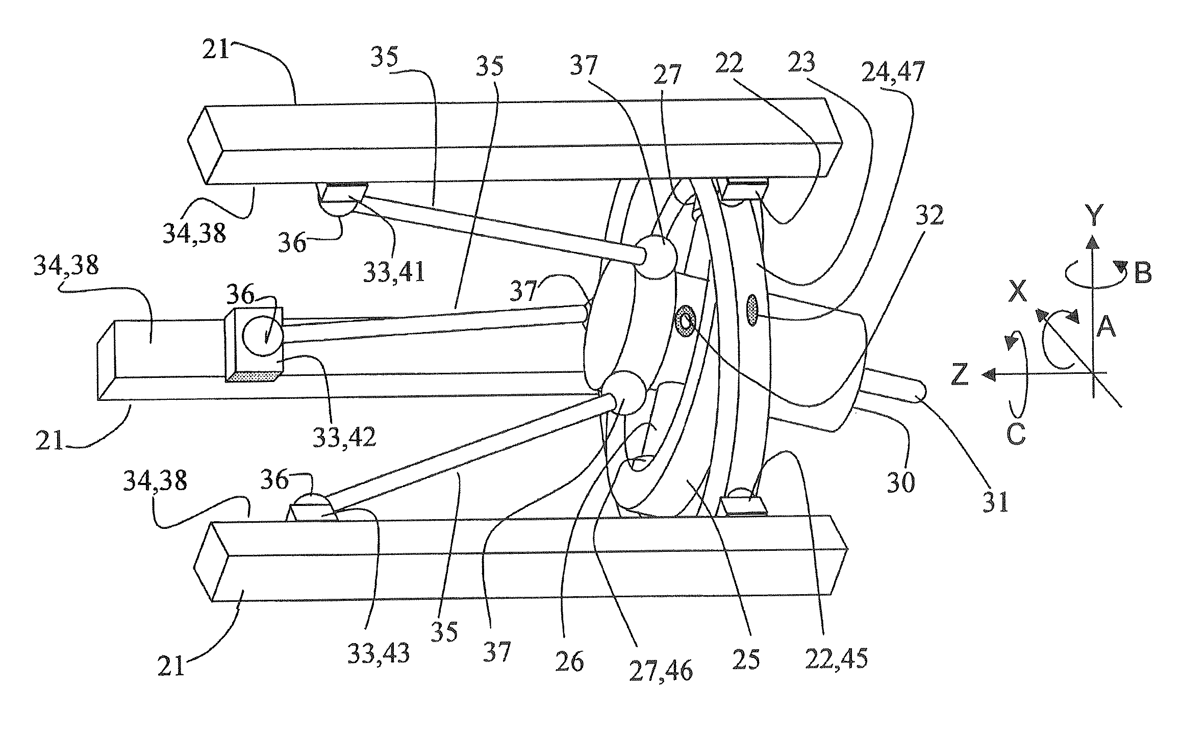
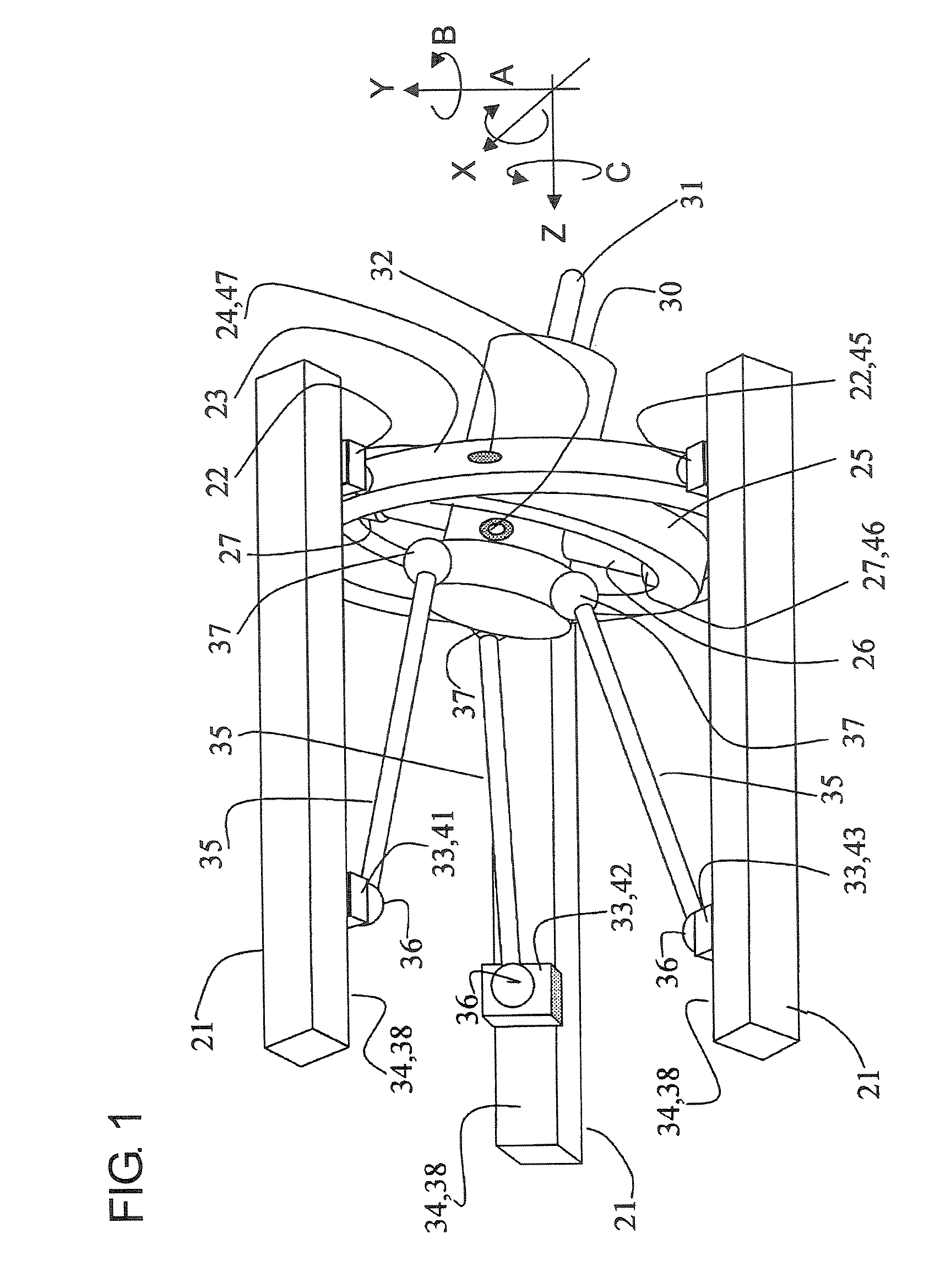
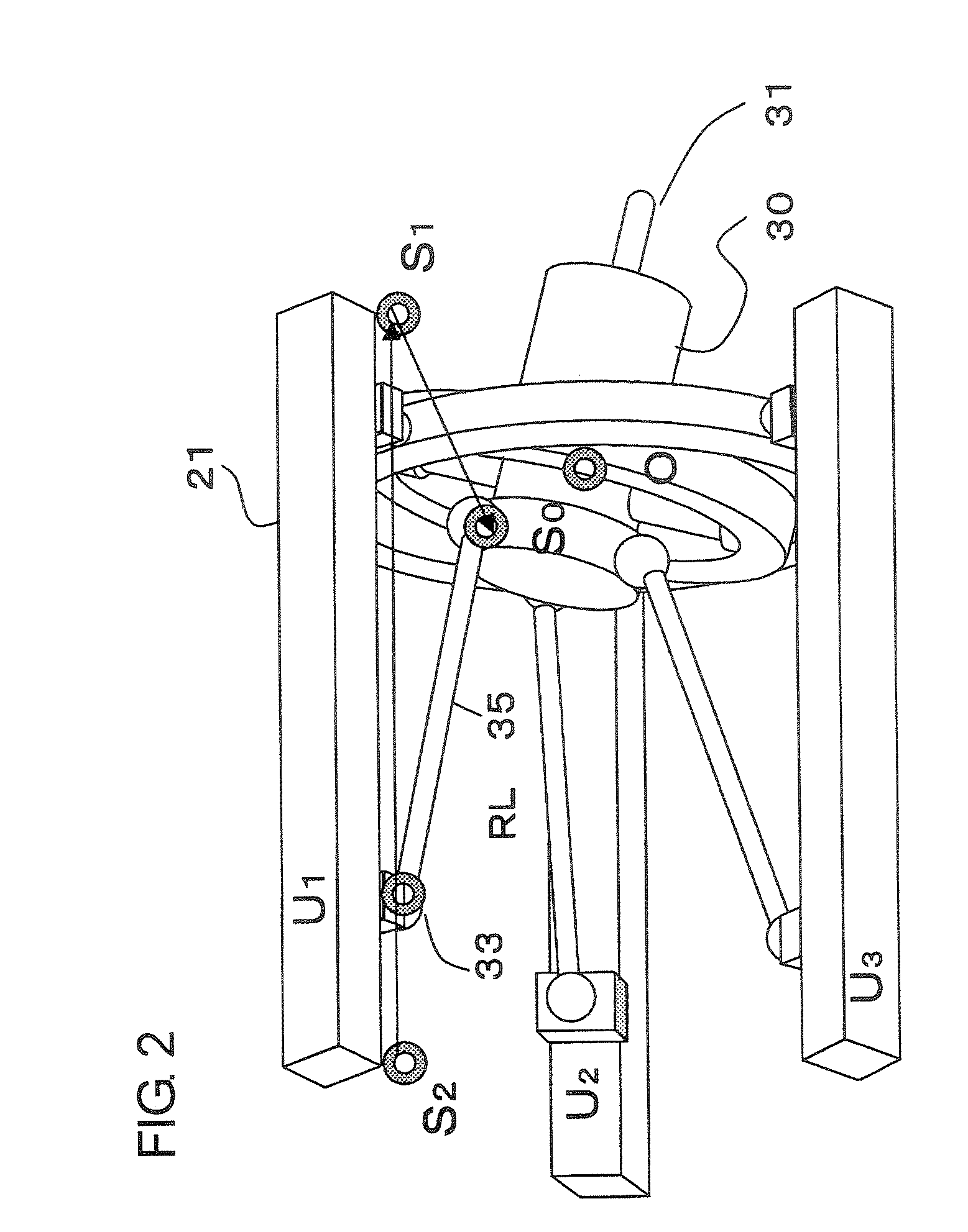
FIG. 1 is a perspective view of a three degree of freedom parallel mechanism in a first embodiment according to the present invention. Three linear guides 21 are secured to an internal surface of a cylindrical housing such as, e.g., that indicated at 94 in FIG. 9. The three linear guides 21 extend in parallel to one another in a Z-axis direction and are circumferentially arranged at equiangular intervals or at 120-degree intervals about an axis parallel to the Z-axis direction. Three follow sliders 22 are provided and guided along the three linear guides 21 to be movable in the Z-axis direction. An annular first movable support member 23 is secured to the three follower sliders 22. Thus, the first movable support member 23 is movable only in the Z-axis direction. A linear encoder 45 is built in one of the three follower sliders 22 to serve as Z-axis position detector for detecting the Z-axis position of the first movable support member 23.

A pair of pivot shafts 24 are provided on th...

second embodiment

FIG. 7 is a perspective view of a three degree of freedom parallel mechanism in a second embodiment according to the present invention. Components which are the same as those in FIG. 1 are designated by the same reference numerals, and description of such components is omitted for the sake of brevity. In this embodiment, the position and orientation of the spindle head 30 are controlled not by the rods 35 but by three telescopic linear actuators 73. The three telescopic linear actuators 73 are attached to a platform 71 through universal joints 72 each having two degrees of freedom. The platform 71 is a part of a housing which is indicated at 94 in FIG. 9 for example or is a member bodily secured to the housing. Each telescopic linear actuator 73 is provided with a drive servomotor 74 with an encoder (not shown), and an output rod 75 of the actuator 73 is telescopically moved in dependence on the rotational position of the drive servomotor 74 with the encoder. The output rods 75 of t...

third embodiment

FIG. 8 is a perspective view of a three degree of freedom parallel mechanism in a third embodiment according to the present invention. Components which are the same as those in FIG. 1 are designated by the same reference numerals, and description of such components is omitted for the sake of brevity. In this embodiment, three rotary actuators 82 are attached to a platform 81, which is a part of a housing which is indicated at 94 in FIG. 9 for example or is a member bodily secured to the housing. Each rotary actuator 82 has built therein a rotary encoder for detecting the rotational position of the rotary actuator 82. A first lever 83 is secured to an output end of each rotary actuator 82 to be pivotable bodily with the same. A universal joint 84 having two degrees of freedom is jointed to an end of each first lever 83, and a second lever 85 is connected to the universal joint 84. The second levers 85 are jointed to rear end portions of a spindle head 30 respectively through spherica...


PUM

PropertyMeasurementUnit
degree of freedomaaaaaaaaaa
degrees of freedomaaaaaaaaaa
bending stressaaaaaaaaaa

Abstract

In a three degrees of freedom parallel mechanism, a spindle head is carried by first and second movable support members to be movable along a Z-axis and to be pivotable along each of A and B-axes. The spindle head is jointed through three rods to drive sliders which are movable along three parallel linear guides secured stationarily. For jointing, there are employed spherical joints and universal joints. Kinematic parameters used in converting each command position of the movable body to target operational positions for three actuators of the Z, A and B-axes are compensated based on inversely converted command positions and inversely converted actually measured positions which have been gathered with the spindle head being located at positions of a suitable number, so that the kinematic parameters can be updated to those newest.

Description

INCORPORATION BY REFERENCEThis application is based on and claims priority under 35 U.S.C. 119 with respect to Japanese Applications No. 2006-099991 and No. 2006-100002 both filed on Mar. 31, 2006, the entire contents of which are incorporated herein by reference.BACKGROUND OF THE INVENTION1. Field of the InventionThe present invention relates to a parallel mechanism for moving and positioning a spindle head or a work table of a machine tool with three degrees of freedom and a control method for the mechanism. In particularly, it relates to a three degree of freedom parallel mechanism and a control method for the mechanism which are suitable for the application to a milling machine for machining aircraft parts or components.2. Discussion of the Related ArtAs parallel mechanisms of this kind, there has been known one which is disclosed in U.S. Pat. No. 6,431,802 and shown in FIG. 10 of the present application. The known mechanism (hereafter referred to as first prior art) is designed...

Claims


Application Information

Patent Timeline
Patent Type & Authority Patents(United States)
IPC IPC(8): B23C1/12B25J9/00
CPCB23Q1/4857B23Q1/5462B25J9/1623B25J17/0266B25J9/0066Y10T74/20341Y10T409/309576Y10T409/307672Y10T74/20317Y10T409/308512
Inventor OTA, HIROMICHI
Owner JTEKT CORP
Why Eureka
Try Eureka