Power converter circuits having bipolar outputs and bipolar inputs

a power converter circuit and output filter technology, applied in power conversion systems, climate sustainability, instruments, etc., can solve the problems of increasing the current, power and thermal stress of the output filter capacitor, reducing the efficiency of the converter, so as to achieve good cm noise performance, simple current sensing mechanism, and high efficiency

Inactive Publication Date: 2011-05-17
WITTENBREDER JR ERNEST H
View PDF3 Cites 16 Cited by
  • Summary
  • Abstract
  • Description
  • Claims
  • Application Information

AI Technical Summary

Benefits of technology

[0008]An object of the subject invention is to reveal new ac input boost converters having higher efficiency than conventional power factor correction boost converters.
[0009]Another object of the subject invention is to reveal new ac input boost converters which can employ a simple current sensing mechanism.
[0010]Another object of the subject invention is to reveal new ac input boost converters having good CM noise performance.
[0011]Another object of the subject

Problems solved by technology

The FIG. 1 circuit accomplishes higher efficiencies by comparison to more conventional boost PFC circuits, but there are some problems associated with the FIG. 1 circuit.
Low common mode noise results because both output filter capacitors have a connection to an ac ground and line neutral.
The FIG. 16 circuit has one s

Method used


Image

  • Power converter circuits having bipolar outputs and bipolar inputs
  • Power converter circuits having bipolar outputs and bipolar inputs
  • Power converter circuits having bipolar outputs and bipolar inputs

Examples


Embodiment Construction

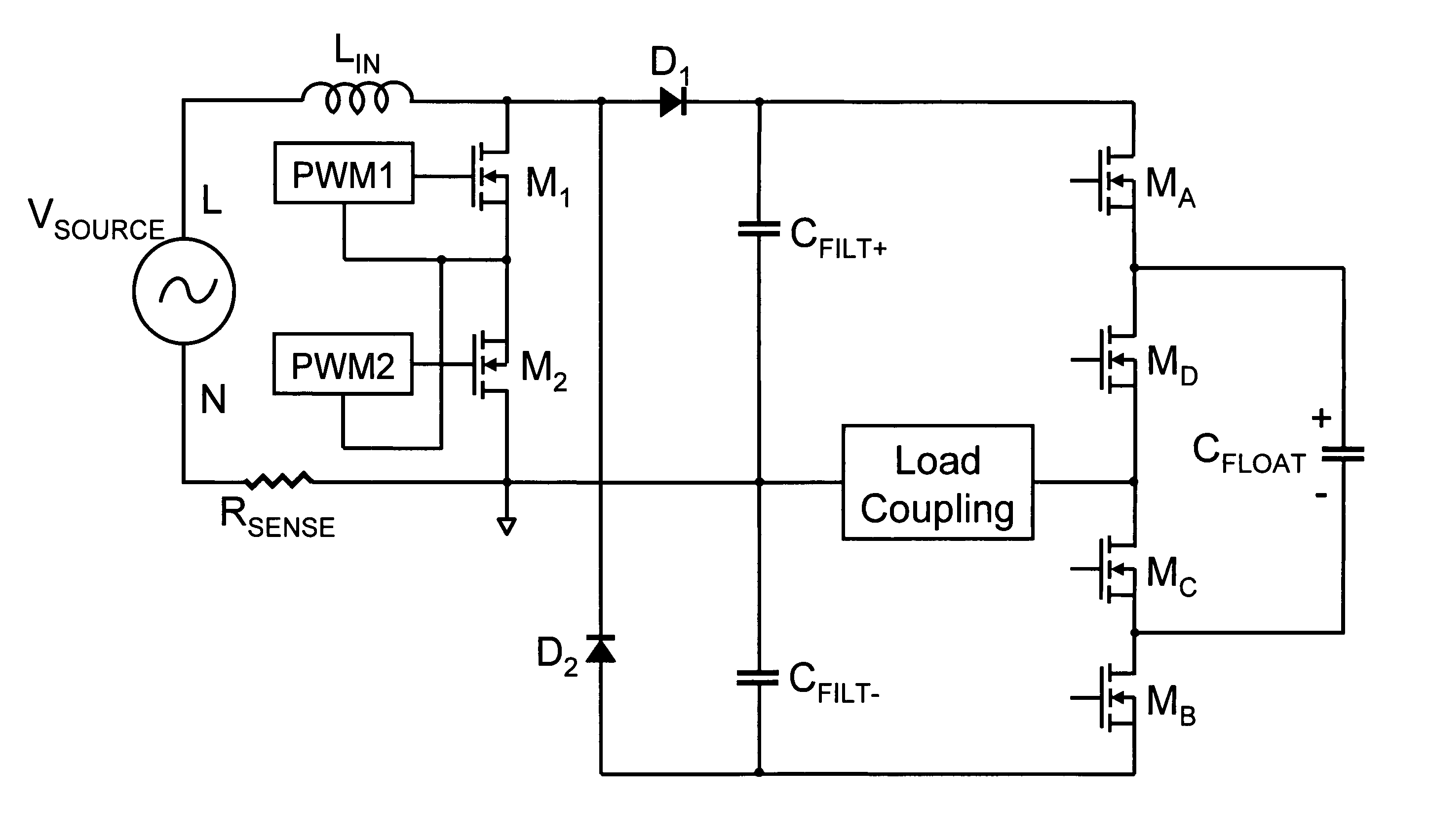
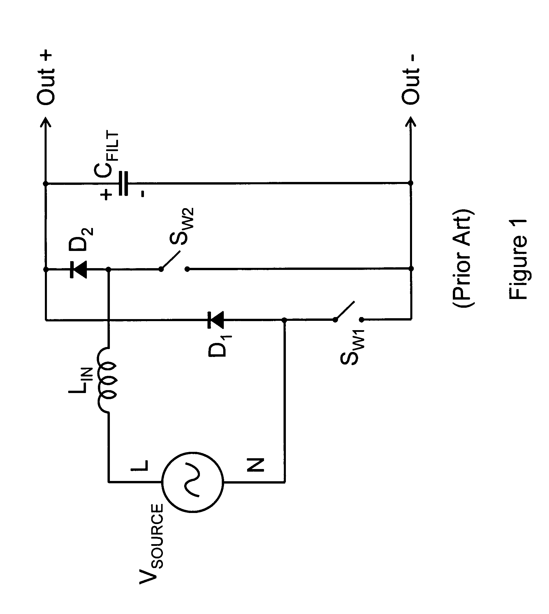
[0060]FIG. 5 illustrates an ac input bipolar output boost converter according to the subject invention. In FIG. 5 an input series network comprising an ac source of voltage, current, and power, VSOURCE, is connected to an input series inductance, LIN. LIN may be either a discrete series inductor or an inherent series inductance of the source of ac power. A first terminal of the series input network is connected to an output neutral terminal. A first main terminal of a switch SW is connected to a second terminal of the input series network and a second main terminal of switch SW is connected to a first terminal of the input series network. An anode terminal of a rectifier switch D1 is connected to the second terminal of the input series network. A cathode terminal of D1 is connected to a positive dc output terminal. An anode terminal of a rectifier switch D2 is connected to a negative dc output terminal and a cathode terminal of rectifier switch D2 is connected to the second terminal...


PUM


Abstract

A new bipolar output boost converter for ac input applications is revealed. The new boost converter is bridgeless, i.e., it does not require use of a line frequency diode rectifier which improves the efficiency of the converter significantly. The new bipolar boost converter does not include the common mode noise generating mechanisms of prior art ac input bridgeless boost rectifier circuits, thereby easing electromagnetic compatibility problems. Although the new converter requires two output filter capacitors, total capacitor stored energy is the same as other boost converters of the same power level so that capacitor volume and cost is not significantly adversely effected. Zero voltage switching cells which can be substituted for a switch to eliminate first order switching losses are also revealed. New three terminal bipolar input source switching networks having operating properties similar to conventional full bridge source switching networks are also revealed.

Description

CROSS REFERENCE TO RELATED APPLICATIONS[0001]This application claims the benefit of PPA Ser. No. 60 / 986,524 filed 2007 Nov. 8 by the present inventor.BACKGROUND OF THE INVENTION[0002]1. Field of the Invention[0003]The subject invention generally pertains to electronic power conversion circuits, and, more specifically, to high frequency, switched mode electronic power converters. The subject matter relates to new boost power converter circuit topologies having bipolar outputs used for ac to dc power conversion and to power converter topologies having bipolar inputs.[0004]2. Description of Related Art[0005]Bridgeless power factor correction (PFC) boost converters have been known for some time. With the recent establishment of high efficiency legal mandates for power supplies they have become more popular. An example of a prior art bridgeless PFC boost converter is illustrated in FIG. 1. The FIG. 1 circuit does not employ a bridge rectifier, but rather uses the boost converter's switch...

Claims


Application Information

Patent Timeline
IPC IPC(8): G05F1/10
CPCH02M1/4208H02M7/217Y02B70/126Y02B70/10
Inventor WITTENBREDER, JR., ERNEST HENRY
Owner WITTENBREDER JR ERNEST H
Why Eureka
Try Eureka