Engine and exhaust heating

a technology of engine and exhaust, applied in the direction of machines/engines, non-automatic control, instruments, etc., can solve the problems of increased potential for engine stalls, engine stalls, engine deformation, etc., to improve engine efficiency, accelerate the increase of catalyst temperature, and improve emission performance

Inactive Publication Date: 2011-05-31
FORD GLOBAL TECH LLC
View PDF14 Cites 12 Cited by
  • Summary
  • Abstract
  • Description
  • Claims
  • Application Information

AI Technical Summary

Benefits of technology

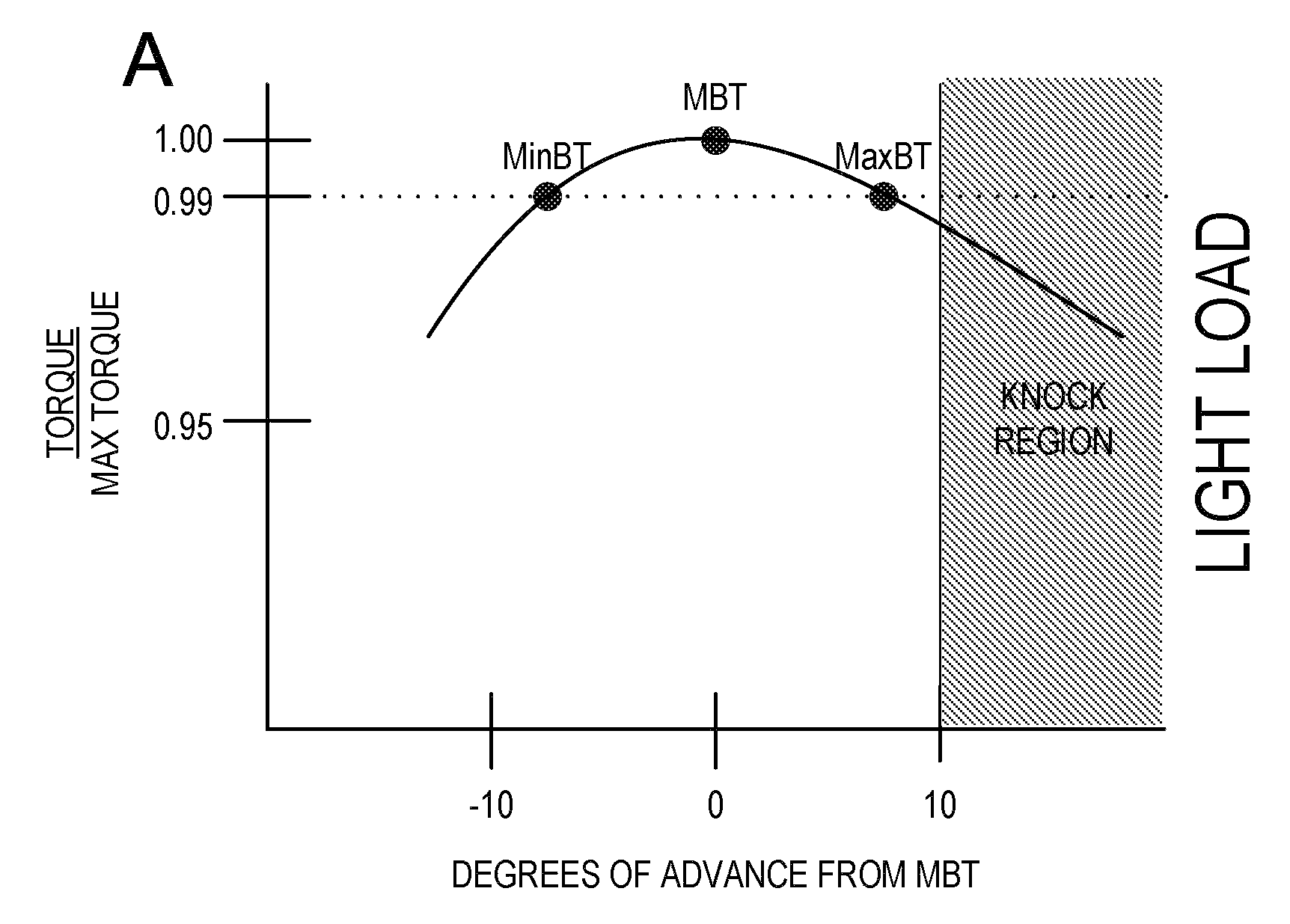
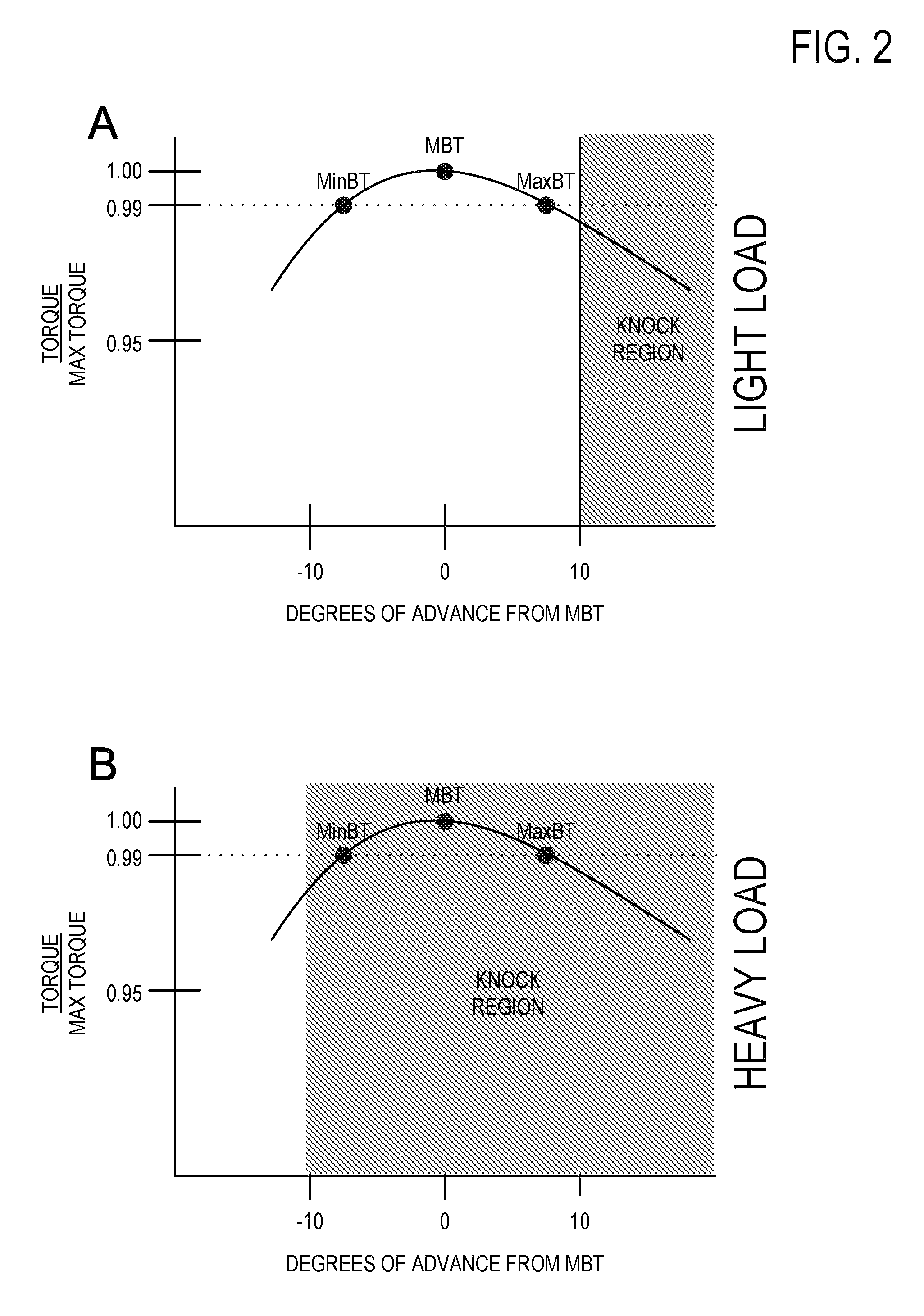
[0002]An engine of a vehicle can operate in an idle condition during stationary or other related vehicle conditions. During cold start engine idle conditions, various systems may utilize waste engine heat to hasten engine warm-up, thereby enabling improved emission performance, engine efficiency, etc. As one example, waste exhaust heat may be adjusted to more rapidly increase catalyst temperature, thereby reducing emissions. Likewise, waste heat in the engine cooling system and / or lubricating system may be directed to the cabin for cabin heating or to the lubricating system, thereby reducing lubricant viscosity thus reducing friction. For example, spark timing may be retarded from MBT during initial starts to first heat an exhaust catalyst, and then once the catalyst is heated, spark timing may be advanced to before MBT to more rapidly heat engine coolant and / or lubricants to thereby provide increased engine efficiency.
[0006]By taking advantage of the torque reserve generated by the advanced spark timing used for increasing heat to engine coolant and / or lubricant, it is possible to improve idle speed control under such conditions. For example, by retarding spark timing in response to a drop in engine speed (while remaining advanced relative to MBT), it is possible to provide a rapid increase in engine torque, with only minor and likely temporary effects on heat delivered to the engine coolant and / or lubricant. As such, improved idle engine speed control can be achieved with reduced stalls while warming the engine. For example, the above approach can provide quick-acting torque reserve with the option of directing waste engine heat to the exhaust or the engine coolant, respectively. In this example, the directional choice of waste heat delivery can be achieved without impacting the level of torque and while maintaining torque reserve.

Problems solved by technology

As one example, at idling conditions when heating the engine coolant via advance timing past MBT, idle speed control may degrade.
In particular, if spark timing is further advanced from an advanced timing relative to MBT in response to speed drops, the potential for engine stalls may increase.
If engine torque decreases too rapidly while the engine is decelerating or while entering idle conditions, the engine may stall.

Method used


Image

  • Engine and exhaust heating
  • Engine and exhaust heating
  • Engine and exhaust heating

Examples


Embodiment Construction

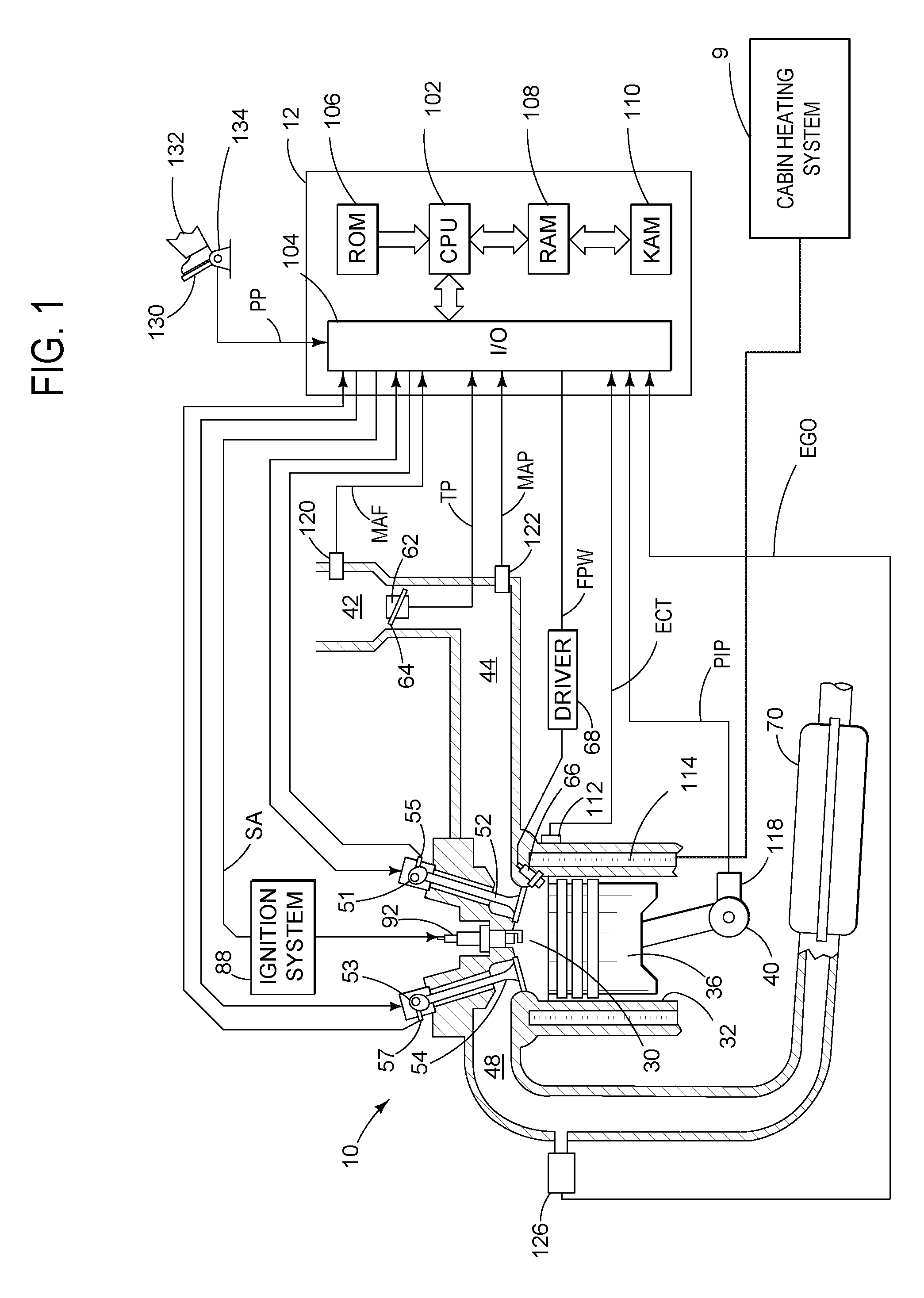
[0014]FIG. 1 is a schematic diagram showing one cylinder of multi-cylinder engine 10, which may be included in a propulsion system of a vehicle. Engine 10 may be controlled at least partially by a control system including controller 12 and by input from a vehicle operator 132 via an input device 130. In this example, input device 130 includes an accelerator pedal and a pedal position sensor 134 for generating a proportional pedal position signal PP. Combustion chamber (cylinder) 30 of engine 10 may include combustion chamber walls 32 with piston 36 positioned therein. Piston 36 may be coupled to crankshaft 40 so that reciprocating motion of the piston is translated into rotational motion of the crankshaft. Crankshaft 40 may be coupled to at least one drive wheel of a vehicle via an intermediate transmission system. Further, a starter motor may be coupled to crankshaft 40 via a flywheel to enable a starting operation of engine 10.

[0015]Combustion chamber 30 may receive intake air fro...


PUM


Abstract

A method for controlling a vehicle engine having a plurality of cylinders is provided. The method comprises: during engine idling, advancing spark timing of at least one cylinder to before a peak torque timing, and retarding spark timing from the advanced timing toward the peak torque timing in response to decreased engine speed to maintain idling speed.

Description

FIELD[0001]The present application relates to a system for controlling idle engine speed control after a cold start.BACKGROUND AND SUMMARY[0002]An engine of a vehicle can operate in an idle condition during stationary or other related vehicle conditions. During cold start engine idle conditions, various systems may utilize waste engine heat to hasten engine warm-up, thereby enabling improved emission performance, engine efficiency, etc. As one example, waste exhaust heat may be adjusted to more rapidly increase catalyst temperature, thereby reducing emissions. Likewise, waste heat in the engine cooling system and / or lubricating system may be directed to the cabin for cabin heating or to the lubricating system, thereby reducing lubricant viscosity thus reducing friction. For example, spark timing may be retarded from MBT during initial starts to first heat an exhaust catalyst, and then once the catalyst is heated, spark timing may be advanced to before MBT to more rapidly heat engine...

Claims


Application Information

Patent Timeline
Patent Type & Authority Patents(United States)
IPC IPC(8): F02P5/00F02P5/02
CPCF02P5/1508F02P5/1506Y02T10/46F02P5/152Y02T10/40
Inventor PURSIFULL, ROSS DYKSTRASURNILLA, GOPICHANDRATRASK, NATE
Owner FORD GLOBAL TECH LLC
Why Eureka
Try Eureka