
Facial bone contouring device using hollowed rasp provided with non-plugging holes formed through cutting plane

a facial bone contouring and hollowed rasp technology, applied in the field of facial bone contouring devices, can solve the problems of excessive bleeding of the cutting site, severe swelling, and difficult to achieve accurate bone cutting, and achieve the effect of preventing the aggregation of bone fragments and removing heat generated in bone cutting

Active Publication Date: 2011-06-07
LEE HEE YOUNG
View PDF34 Cites 7 Cited by
  • Summary
  • Abstract
  • Description
  • Claims
  • Application Information

AI Technical Summary

Benefits of technology

[0022]Therefore, the present invention has been made in view of the above problems of the conventional surgical cutting instruments, and it is an object of the present invention to provide a facial bone contouring device using a rasp, which can be inserted beneath the skin via a small-sized incision and continuously cut bone at a cutting site into very small fragments, thus easily controlling the cutting amount of bone and drastically reducing the risk of medical accidents.
[0024]It is yet another object of the present invention to provide a device for continuously and stably exhausting a large quantity of bone, periosteum and muscles at a high speed, in surgery in which a large quantity of bone, periosteum and muscles must be removed in a short period of time such as facial bone contouring surgery.
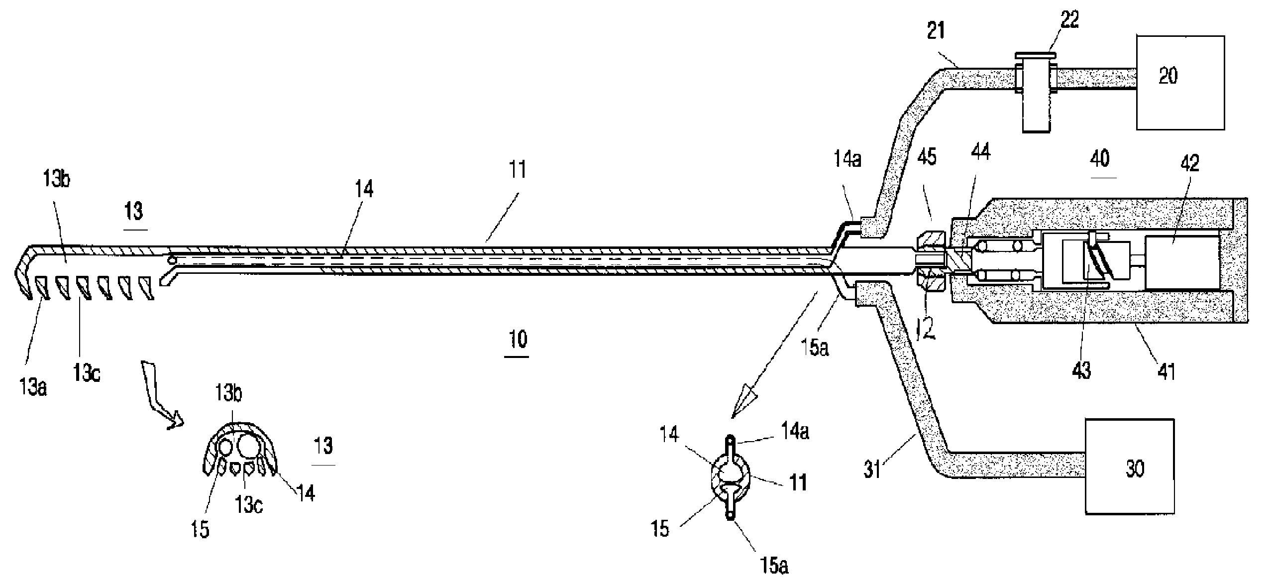
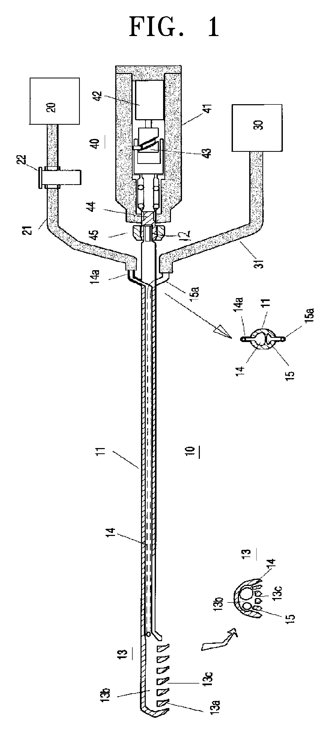
[0032]The fed saline solution serves to remove heat generated in bone-cutting so that the cutting can be continuously performed, and to prevent the aggregation of the bone fragments due to frictional heat so that the bone fragments are thoroughly exhausted to the outside.

Problems solved by technology

Since a large quantity of bone is cut using such a saw at once, the accuracy in bone cutting is difficult to achieve.
Accordingly, the conventional method has several problems such as severe swelling and excessive bleeding of the cutting site, delayed healing, cutting of vessels, nerve damage, etc.
Further, the saw for cutting bone may cause severe injuries to peripheral soft tissues around the incision during the movement.
However, since there is not yet developed any device to meet this requirement, it is difficult to stably perform surgery using the rasp.
Since bone fragments are accumulated, aggregated and compressed between blades of the conventional rasp during the operation, continuous cutting using the rasp is impossible.
Thus, since blades of electric-powered or pneumatic rasps must be cleaned off every several seconds, it is impossible to grind a large amount of bone using these rasps in the facial bone contouring surgery.
Further, the stacking of the bone fragments on the blades is made more severe by heat generated from the cutting plane of the electric-powered or pneumatic rasps.
On the other hand, hand-powered rasps do not generate heat but have a low operational speed, thus being impractical to use.
The conventional electric-powered or pneumatic devices cannot be inserted under the skin via a small incision so as to continuously grind a large amount of bone.
These conventional devices have limitedly been used to remove a small amount of bone.
However, these devices have a structure which cannot be used in facial bone contouring surgery.
However, the conventional devices do not meet these requirements, thus not being used in facial bone contouring surgery.
However, this assembly cannot supply a saline solution to the cutting surface, thus not eliminating heat generated on the cutting surface when a large quantity of bone such as zygomatic bone, maxilla or mandible is continuously removed.
Further, the inlet has a structure such that the continuous cutting of bone cannot be performed and bone debris aggregated and compressed between blades of the rasp cannot be exhausted to the outside, thus requiring frequent cleaning.
Accordingly, this assembly can be used in surgical facial procedures such as rhinoplasty and supraorbital procedures, but cannot be effectively used in the skin overlying the area of the supraorbital bone that is to be reshaped or contoured.
Here, heat is generated due to friction between the rasp and the bone, thus causing damages such as burning of soft tissues or deformation of tissues.
Further, the cut fragments of bone are aggregated during cutting and accumulated between blades of the rasp, thus not being exhausted to the outside and remarkably reducing the cutting efficiency of the assembly.
Since the collected bone fragments are damaged by the heat generated due to friction between the rasp and the bone, it is difficult to use the damaged bone fragments in bone tissue culture.
Further, during the driving of the cutting member, the cutting member irritates and damages peripheral soft tissues around the operative site.
Further, the assembly does not have a double tube structure, thus not protecting peripheral regions around the operative site during the insertion and operation of the rasp, and causing inconvenience to a surgeon in case that the rasp is inserted into the operative site via a small and deep incision.
Since the friction generated between the cutting plane of the rasp operated at a high speed and the bone damages peripheral tissues, this assembly is not suitable for use in facial bone contouring surgery.
However, since heat generated on this cutting means cannot be eliminated and bone crash is accumulated between blades of the cutter, the cutting means is not suitable for use in removal of a large quantity of bone or for facial bone contouring surgery.
However, an inlet does not pass through the cutting plane, thus generating many bone fragments and causing a difficulty in sucking large-sized tissue fragments.
That is, the slits between the blades of the rasp are easily clogged with the cut bone fragments.
Although the saline solution is sprayed via the through-holes, since the spraying pressure of the saline solution is smaller than the suction pressure of the bone fragments, the through-holes are easily clogged with the bone fragments.
However, the above structure does not meet this requirement.
Further, with the above structure, it is impossible to form the maximum cutting plane via the minimum outer diameter of the cutter.
This hand-powered rasp sucks only air via the openings, but does not feed saline solution for removing generated heat and remove bone fragments at a high speed.
Further, the rasp does not have a double cannula structure, and the size of the openings is not sufficient to suck the cut bone fragments together with air.
Moreover, it is difficult to manufacture a cutter of the rasp being suitable for use in facial bone contouring surgery.
However, the hand-powered vacuum rasp having this suction structure cannot be used in facial bone contouring surgery.
However, these instruments perform the tissue cutting using a rotary blade, thus causing exposed portions of nerves and vessels in facial bone contouring surgery to be dangerously rolled into the blade.
Further, these instruments remove only portions sucked into protrusions or an external pipe, thus not being used in reduction of a broad area such as facial bone contouring surgery.

Method used


Image

  • Facial bone contouring device using hollowed rasp provided with non-plugging holes formed through cutting plane
  • Facial bone contouring device using hollowed rasp provided with non-plugging holes formed through cutting plane
  • Facial bone contouring device using hollowed rasp provided with non-plugging holes formed through cutting plane

Examples


Embodiment Construction

[0041]Now, preferred embodiments of the present invention will be described in detail with reference to the annexed drawings.

[0042]FIG. 1 is a schematic view of a facial bone contouring device in accordance with the present invention. A rasp 10 includes a rod 11, an adaptor connector 12 formed on an end of the rod 11, a cutter 13 formed on the other end of the rod 11, a bone fragment exhausting passage 14, and a saline solution feeding passage 15. The cutter 13 has a cutting blade 13a formed on the lower surface of the cutter 13, a cavity 13b formed in the cutter 13, and a plurality of grooves 13c passing through the cutting blade 13a so as to connect the cutting blade 13a to the cavity 13b. Two independent tubes are formed in the rod 11 and connected to the cavity 13b of the cutter 13, thus serving as the bone fragment exhausting passage 14 and the saline solution feeding passage 15.

[0043]Terminals of the two tubes formed in the rod 11 are connected to the cavity 13b formed in the ...


PUM


Abstract

Disclosed is a facial bone contouring device for use in facial bone contouring surgery and bone tumor and / or osteophyte removal. The facial bone contouring device comprises: a rasp (10), having a double tube structure, including a rod (11), and a cutter (13) provided with plural grooves (13c) for exhausting cut bone fragments, a saline solution feeding passage (15) and a bone fragment exhausting passage (14); a powered surgical handpiece (40) connected to the rasp (10) for providing linear reciprocating motion to the rasp (10); a saline solution feeding unit (30) for feeding saline solution to the saline solution feeding passage; and a suction unit (20) for sucking and exhausting the cut bone fragments, wherein bone cutting is performed under the condition that the saline solution is fed into the rasp, and the cut bone fragments are exhausted together with the saline solution so that the bone cutting is continuously performed.

Description

TECHNICAL FIELD[0001]The present invention relates to a contouring device for use in facial bone contouring surgery such as mandibular angle reduction and maloplasty, and removal of bone tumor and / or osteophyte, and more particularly to a facial bone contouring continuous cutting device using a small-sized rasp, which is able to be inserted beneath the skin and cut bone, provided with bone fragment exhausting means and saline solution feeding means and attached to a handpiece with linear reciprocating means, which can be inserted beneath the skin through a minimum-sized incision and delivered to a bone cutting site to carry out facial bone contouring surgery.BACKGROUND ART[0002]Generally, a conventional method used in facial bone contouring surgery employs a bone-cutting saw for cutting bone at a desired site. Since a large quantity of bone is cut using such a saw at once, the accuracy in bone cutting is difficult to achieve.[0003]In order to accurately set a cutting angle, easily e...

Claims


Application Information

Patent Timeline
Patent Type & Authority Patents(United States)
IPC IPC(8): A61B17/32A61B17/16A61B19/00A61M1/00
CPCA61B17/1659A61B17/1633A61B2217/005A61B2017/320028A61B2019/481A61B17/1671A61B2090/08021A61B17/16
Inventor LEE, HEE-YOUNG
Owner LEE HEE YOUNG
Learn More