Contactless energy supply for moving consumers

a technology of moving consumers and energy supply, applied in the direction of electric vehicles, large fixed members, emission reduction of energy storage, etc., can solve the problems of increasing the cost of components in extreme ways, requiring regular maintenance, and saving additional material expenditure and manufacturing and assembly costs, so as to increase the complexity of energy supply and efficient use

Inactive Publication Date: 2011-06-14
REXROTH INDRAMAT
View PDF22 Cites 6 Cited by
  • Summary
  • Abstract
  • Description
  • Claims
  • Application Information

AI Technical Summary

Benefits of technology

[0005]This object is attained by the present invention which ensures a contactless energy transmission that satisfies all the points required, and especially ensures the required maintenance friendliness, since hardly any additional mechanical system is involved. Because of the induced voltage of an additional energy supply field in the field-generating coils used for generating the propulsion field (traveling field), and the utilization of a linear motor component (primary part) that is pre-existing, and that is connected therewith, this arrangement saves the additional material expenditure and manufacturing and assembly costs. The secondary part and the primary part of the linear motor do not have to be enlarged by mechanical components (inductance loops, auxiliary windings, etc.), in the design approach according to the present invention. Only an additional energy transmitting interface is required. Also, an expansion, from a circuit technology point of view, of the coil feeding for the induction of the required electrical field required for the energy transmission into the field-generating windings has to be undertaken. However, these measures result in relatively low costs.
[0006]The consumers may be functional blocks for propulsion regulation and motion regulation, as well as data processing devices for position recording and the sensors connected with that, and / or means for communications. This makes the device very flexible overall, with respect to the conceivable fields of use. A plurality of embodiments are conceivable and implementable, from complex transportation, packaging and automation devices having a plurality of independently driven secondary parts all the way to the implementation of a simple linear motion.

Problems solved by technology

Disadvantages of the system are that, on the one hand, the inductive energy coupling is not without gaps along the route, and, on the other hand, for the generation of an alternating field of high frequency, generally an additional expenditure for material, manufacturing and costs for the implementation is required, which increases in proportion to the route length, and therewith makes the components more expensive in an extreme manner (see, e.g., FIG. 6; column 11, lines 14 ff), as well as requiring regular maintenance.
Consequently, similar disadvantages derive from this U.S. patent document as in the case of the arrangement described in European patent document EP 0580 107.
Because of the induced voltage of an additional energy supply field in the field-generating coils used for generating the propulsion field (traveling field), and the utilization of a linear motor component (primary part) that is pre-existing, and that is connected therewith, this arrangement saves the additional material expenditure and manufacturing and assembly costs.
However, these measures result in relatively low costs.
The arbitrary supplying with current of all coils increases the heat or energy losses, and thereby also reduces the durability and the service life.
Without these measures, no data with respect to the location of the secondary parts would be available in the case of a central control after the (re)starting of the system, because for lack of present energy, the systems mounted on the secondary part do not work yet.
In the case of a collision or a derailment of the secondary part, however, protection of these data could also be useless.
Only then is the system again ready for use, and the secondary parts can again arrive at their original position, which is a time-consuming procedure, and, with regard to the effects of downtime in highly optimized manufacturing processes, a very expensive one.
A plurality of secondary parts cause increased complexity in the energy supply.

Method used


Image

  • Contactless energy supply for moving consumers
  • Contactless energy supply for moving consumers
  • Contactless energy supply for moving consumers

Examples


Embodiment Construction

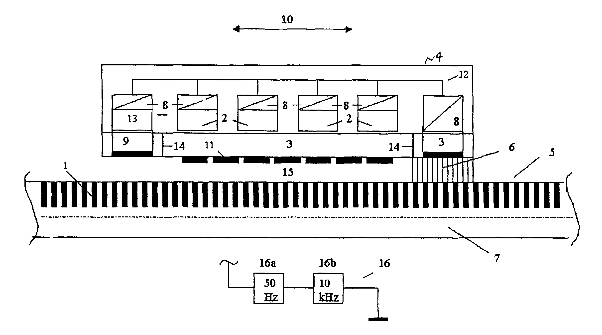
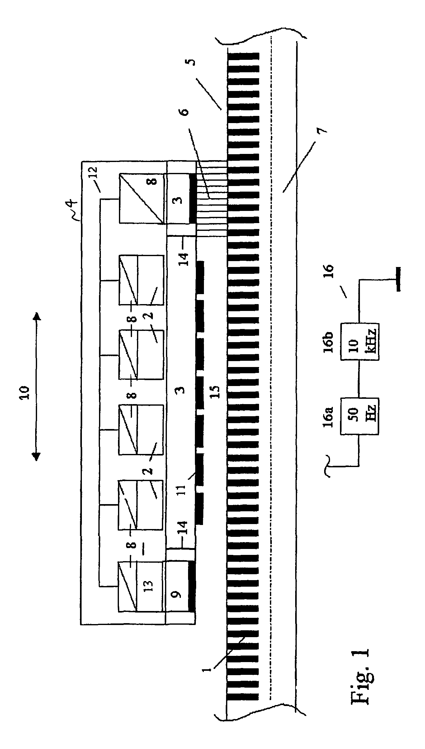
[0025]The linear motor shown in FIG. 1 is made up of a secondary part / secondary parts 4 (only one shown here for clarity sake) and a primary part / primary parts 5, which form a motion path (only one segment shown here for clarity sake). The overall arrangement is shown in a cross-section which is parallel to the possible direction of motion 10 along the center axis. Permanent magnets 11 are situated on the lower side of secondary part 4, which is opposite primary part 5. The field of this permanent magnet 11 interacts with the propulsion field or moving field of field-generating coils 1 and secondary part 4, because of the resulting Lorentz force. On the upper side of secondary part 4, consumers 2 are situated which are supplied with energy using voltage and / or level converter 8. In this example, energy supply interface 3 is docked to the secondary part on a side 14 that extends transversely to the direction of motion. Energy interface 3 could in principle be mounted at any other pla...


PUM


Abstract

A contactless energy supply for electrical consumers mounted on the mobile part of a linear motor is provided, the energy supply being provided without additional voltage sources. A higher frequency energy supply field is superposed over the propulsion field, the energy supply field being inductively decoupled using the energy transmitting interface of the secondary part, and supplying consumers mounted on the secondary part with energy.

Description

FIELD OF THE INVENTION[0001]The present invention relates to supplying electrical loads (or consumers) on the secondary part (moving part) of a linear motor.BACKGROUND INFORMATION[0002]European Patent document EP 0580 107 shows a magnetic suspension system which is designed for transport purposes using straight and curved path sections. The crucial point, in this instance, is the control of the air gap, as a function of the load of the secondary part, using a regulating device fixed to the secondary part. This regulation device is supplied with energy in a contactless manner, via an induction loop having a 10 kHz voltage source. The induction loop is, however, only present at the straight route sections. For travel on curves, a back-up battery situated on the suspension vehicle has to provide energy. Disadvantages of the system are that, on the one hand, the inductive energy coupling is not without gaps along the route, and, on the other hand, for the generation of an alternating fi...

Claims


Application Information

Patent Timeline
Patent Type & Authority Patents(United States)
IPC IPC(8): B60L13/00B23Q1/00H02P25/06
CPCH02P25/06B23Q1/0009Y02P90/50
Inventor SCHEMM, EBERHARDSCHNURR, BERND
Owner REXROTH INDRAMAT
Why Eureka
Try Eureka