Motor drive system for railway vehicle
a technology for railway vehicles and motors, applied in the direction of motor/generator/converter stoppers, multiple dynamo-motor starters, electric devices, etc., can solve the problems of limited arranging of inverters as close to the motor, malfunction of railway signals, and general bulkyness, and achieve low capacity, suppress current ripple, and reduce the effect of vibration
- Summary
- Abstract
- Description
- Claims
- Application Information
AI Technical Summary
Benefits of technology
Problems solved by technology
Method used
Image
Examples
first embodiment
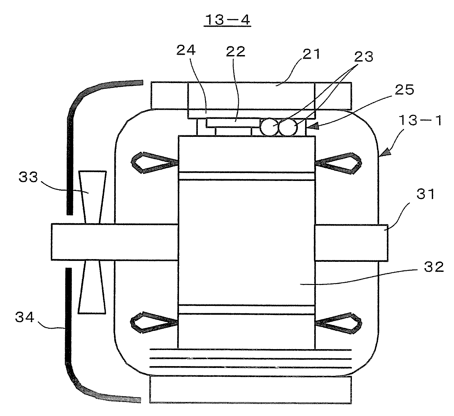
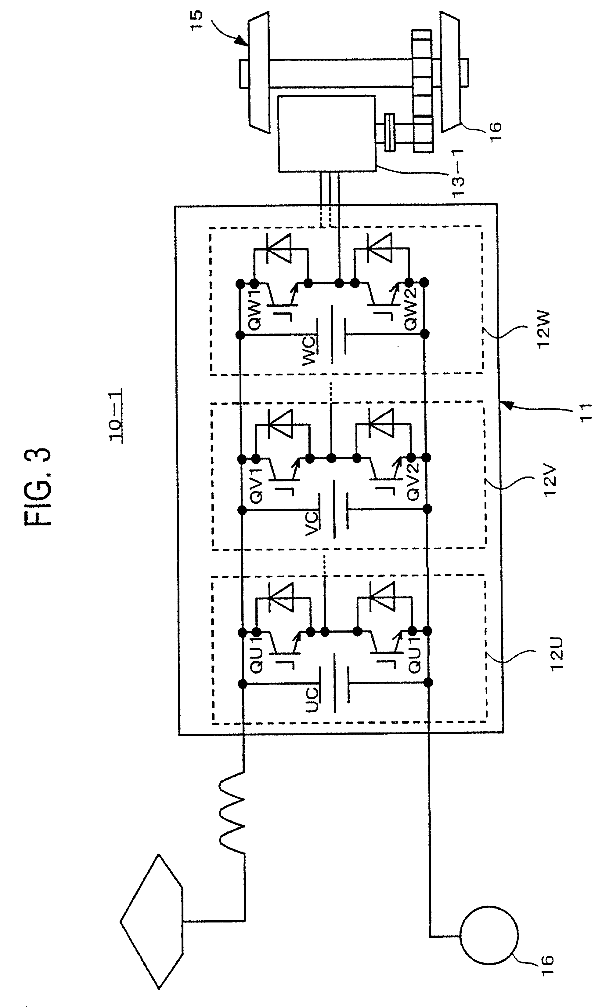
[0031]A motor drive system for a railway vehicle according to the first embodiment of the present invention will be explained with reference to FIGS. 3 to 5. The motor drive system 10-1 according to the first embodiment includes a three-phase inverter 11 and a three-phase, permanent-magnet synchronous motor 13-1. The inverter 11 includes a U-phase unit 12U having two pairs of U-phase switching elements, a V-phase unit 12V having two pairs of V-phase switching elements, and a W-phase unit 12W having two pairs of W-phase switching elements.
[0032]The U-phase unit 12U has two IGBTs (Insulated Gate Bipolar Transistors) QU1 and QU2 and a capacitor UC and forms an arm of the two-level inverter 11. Each of the V- and W-phase units 12V and 12W is similarly formed.
[0033]As shown in detail in FIG. 5, the U-, V-, and W-phase units 12U, 12V, and 12W are mechanically separated from one another and are arranged on the surface of the motor 13-1. As shown in detail in FIG. 3, direct-current parts of...
second embodiment
[0036]A motor drive system for a railway vehicle according to the second embodiment of the present invention will be explained with reference to FIGS. 6 and 7. The motor drive system 10-2 of the second embodiment includes a first inverter 11-1, a second inverter 11-2, a third inverter 11-3, and a three-phase, three-winding, permanent-magnet synchronous motor 13-2.
[0037]As shown in FIG. 6, the first inverter 11-1 is a two-level, full-bridge inverter having six IGBT switching elements and a capacitor. Generally, railway vehicles employ a DC voltage of 1500 V, and therefore, IGBTs each having a withstand voltage of 3300 V are usually adopted. On the contrary, the six IGBT switching elements employed by the second embodiment for each inverter are each of a withstand voltage of 1200 V. The IGBT switching elements of 1200-volt withstand voltage are widely available for, for example, hybrid electric cars, and therefore, are inexpensive. The second and third inverters 11-2 and 11-3 are cons...
third embodiment
[0041]A motor drive system for a railway vehicle according to the third embodiment of the present invention will be explained with reference to FIGS. 8 to 11.
[0042]As shown in detail in FIG. 8, the motor drive system 10-3 of the third embodiment includes a first inverter 11A, a second inverter 11B, and a six-phase, permanent-magnet synchronous motor 13-3. The first inverter 11A is a two-level, full-bridge inverter having six IGBT switching elements and a capacitor. The second inverter 11B is constituted like the first inverter 11A. Direct-current ends of the first and second inverters 11A and 11B are connected in parallel, to receive a voltage from an overhead line.
[0043]As shown in detail in FIG. 9, the first and second inverters 11A and 11B are mechanically separated from each other and are arranged on the surface of the motor 13-3. Alternating-current output ends of each of the inverters 11A and 11B are connected to phase input terminals of the motor 13-3. The integrated structur...
PUM
 Abstract
Description
Claims
Application Information
 - R&D
- Intellectual Property
- Life Sciences
- Materials
- Tech Scout
- Unparalleled Data Quality
- Higher Quality Content
- 60% Fewer Hallucinations
Browse by: Latest US Patents, China's latest patents, Technical Efficacy Thesaurus, Application Domain, Technology Topic, Popular Technical Reports.
© 2025 PatSnap. All rights reserved.Legal|Privacy policy|Modern Slavery Act Transparency Statement|Sitemap|About US| Contact US: help@patsnap.com


