Stator resistance adaptation in sensorless PMSM drives

a technology of stator resistance and pmsm, which is applied in the direction of motor/generator/converter stopper, electric controller, dynamo-electric converter control, etc., can solve the problems of inaccuracy of estimated resistance value, inability to accurately estimate position estimation accuracy, and inability to operate at low speeds in a loaded condition. achieve accurate stator resistance estimate, greatest effect on control quality

Active Publication Date: 2011-06-28
ABB (SCHWEIZ) AG
View PDF1 Cites 13 Cited by
  • Summary
  • Abstract
  • Description
  • Claims
  • Application Information

AI Technical Summary

Benefits of technology

[0009]An advantage of the method of the invention is the accurate stator resistance estimate that is obtained in a simple manner from a signal already present in the control system. The more accurate stator resistance estimate enables a more accurate control of PMSM especially at the low speed region, where the influence of an erroneous stator resistance estimate has the greatest effect on the quality of the control.

Problems solved by technology

The erroneous stator resistance results in an incorrect back-emf estimate, and consequently, impaired position estimation accuracy.
The operation can also become unstable at low speeds in a loaded condition.
The problem relating to the known resistance estimation methods is the inaccuracy of the estimated resistance value.

Method used


Image

  • Stator resistance adaptation in sensorless PMSM drives
  • Stator resistance adaptation in sensorless PMSM drives
  • Stator resistance adaptation in sensorless PMSM drives

Examples


Embodiment Construction

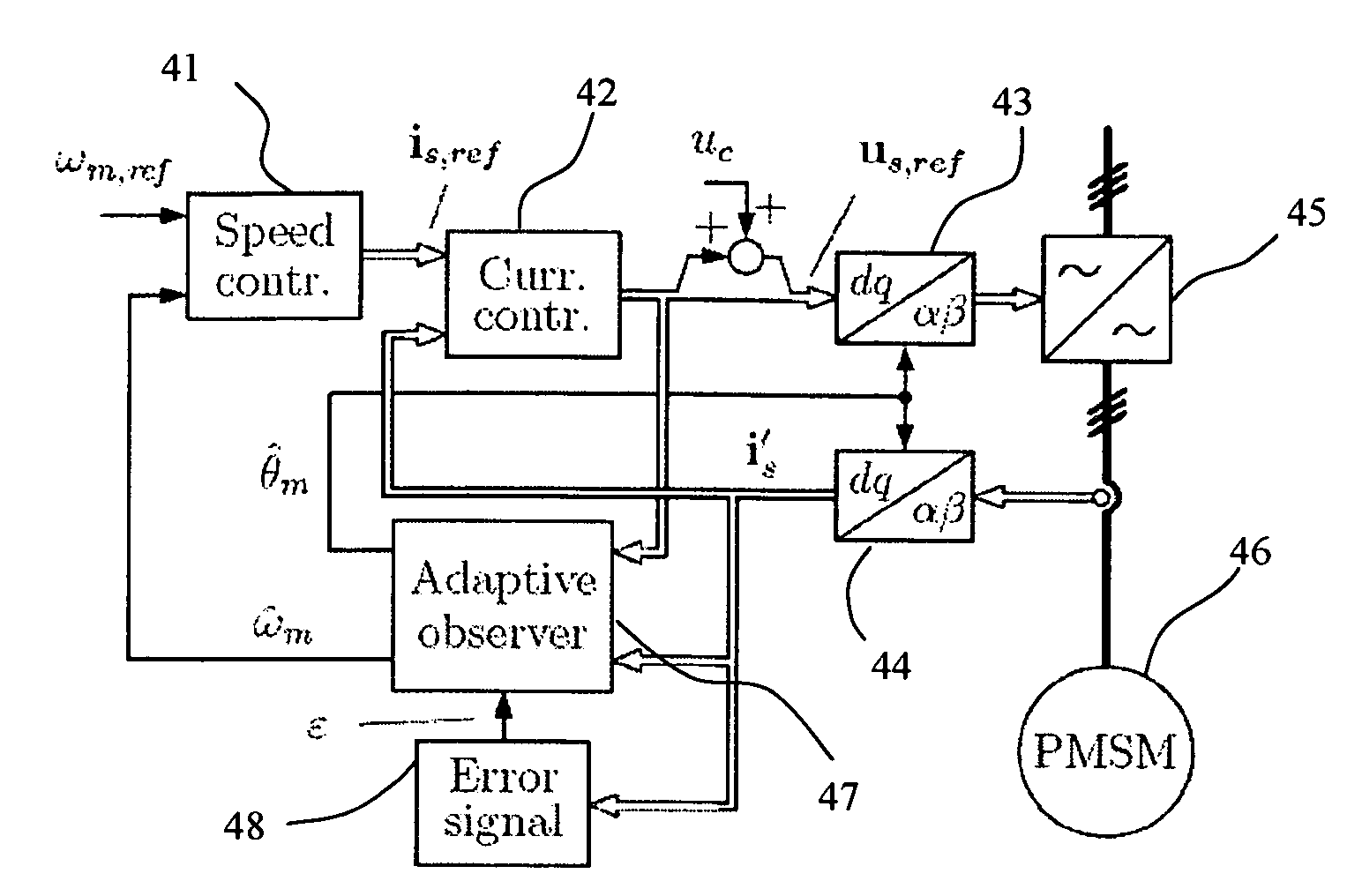
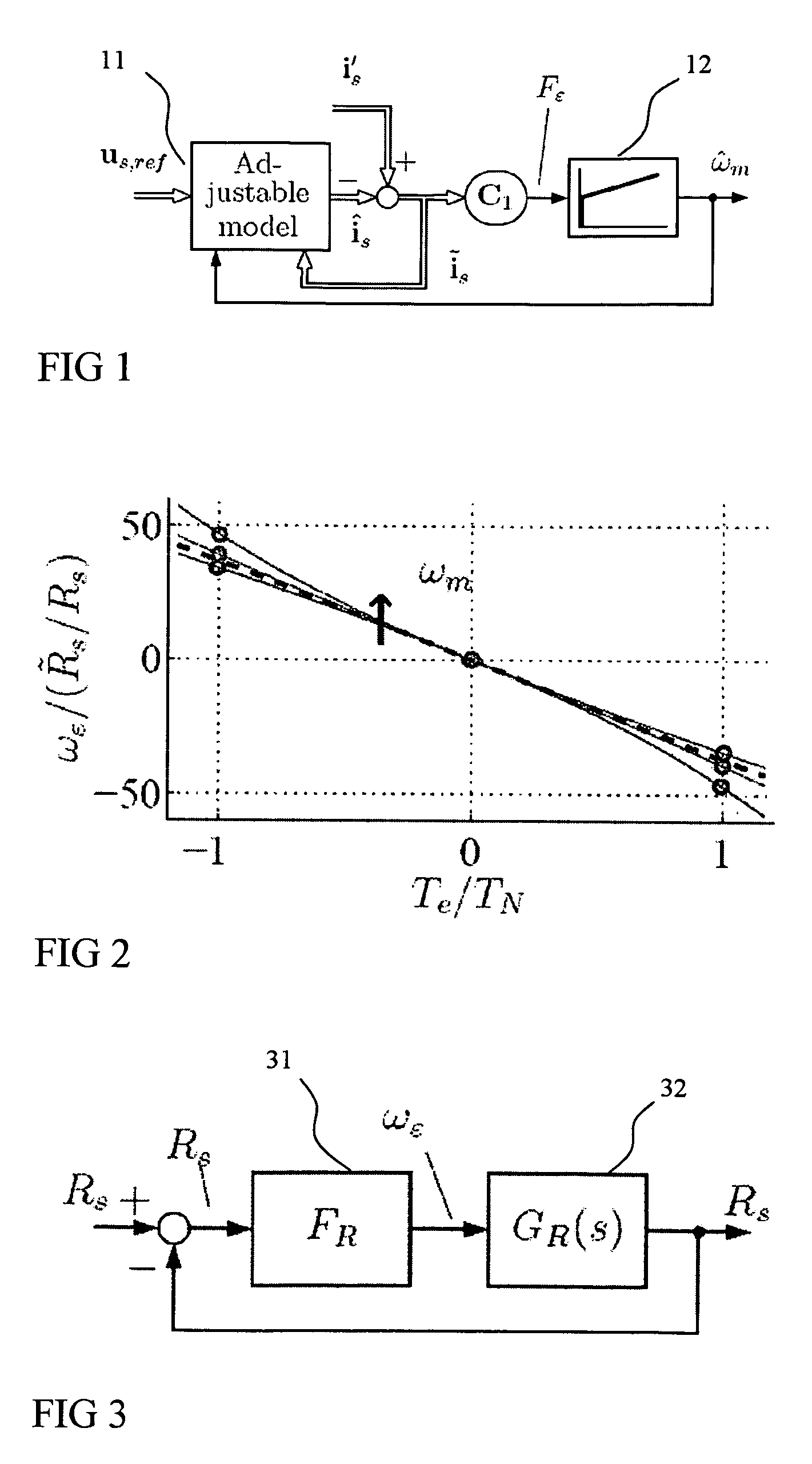
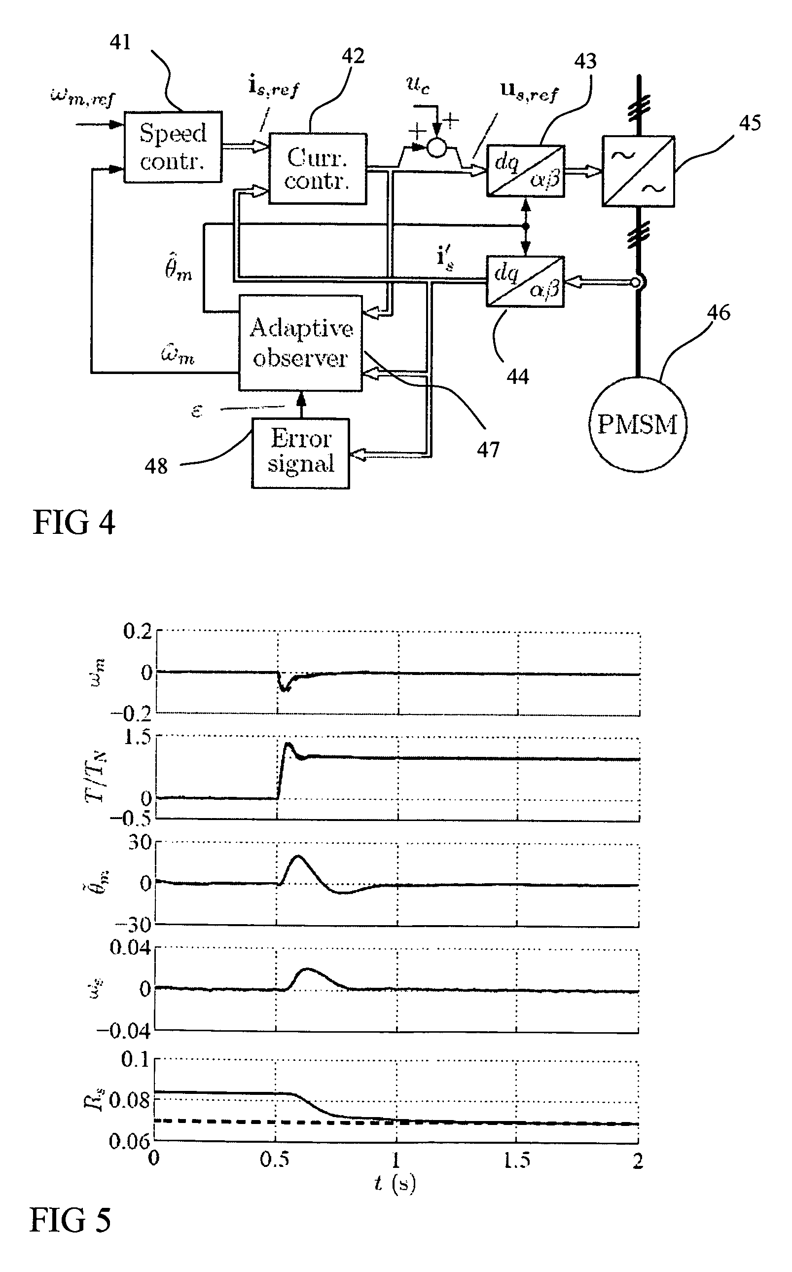
[0016]In the description, first a model for a permanent magnet synchronous machine is given. Then adaptive observer is shortly discussed together with high-frequency signal injection. The model and observer are both known per se, but since the method of the present invention is based on these, the short descriptions are provided for better understanding of the invention.

[0017]The PMSM is modeled in the d-q reference frame fixed to the rotor. The d axis is oriented along the permanent magnet flux, whose angle in the stator reference frame is θm in electrical radians. The stator voltage equation is

us=Rsis+{dot over (ψ)}s+ωmJψs  (1)

where us=[ud uq]T is the stator voltage, is=[id iq]T the stator current, ψs=[ψd ψq]T the stator flux, Rs the stator resistance, ωm={dot over (θ)}m the electrical angular speed of the rotor, and

[0018]J=[0-110]

The Stator Flux is

ωs=Lis+ψpm  (2)

where ψpm=[ψpm 0]T is the permanent magnet flux and

[0019]L=[Ld00Lq]

is the inductance matrix, Ld and Lq being the direct...


PUM


Abstract

A method of estimating stator resistance of a permanent magnet synchronous machine, when the permanent magnet synchronous machine is controlled with an inverter using a control system having an adaptive observer which is augmented with a signal injection, the adaptive observer having a stator resistance estimate ({circumflex over (R)}s) as a parameter, in which method an error signal (ε) is obtained from the signal injection, a speed correction term (ωε) is calculated from the error signal (ε), the rotor position estimate is corrected using the speed correction term (ωε) in the adaptive observer, whereby the error signal (ε) is driven to zero. The method comprises the step of correcting the value of the stator resistance estimate ({circumflex over (R)}s) in the adaptive observer when the speed correction term (ωε) differs from zero.

Description

FIELD OF THE INVENTION[0001]The present invention relates to a method for stator resistance adaptation, and more particularly to a method which can be used to correct the stator resistance estimate of a permanent magnet synchronous machine during the control of the machine.BACKGROUND OF THE INVENTION[0002]Permanent magnet synchronous machines (PMSMs) are used in many high performance applications. For vector control of PMSMs, information on the rotor position is required. In sensorless control, the rotor speed and position can be estimated by fundamental-excitation methods as in [1] R. Wu and G. R. Slemon, “A permanent magnet motor drive without a shaft sensor,” IEEE Trans. Ind. Applicat., vol. 27, no. 5, pp. 1005-1011, September / October 1991 or signal injection methods as in [2] P. L. Jansen and R. D. Lorenz, “Transducerless position and velocity estimation in induction and salient AC machines,” IEEE Trans. Ind. Applicat., vol. 31, no. 2, pp. 240-247, March / April 1995.[0003]The abo...

Claims


Application Information

Patent Timeline
Patent Type & Authority Patents(United States)
IPC IPC(8): G05B11/36
CPCH02P21/13H02P21/14H02P23/14H02P23/12H02P21/145H02P21/16
Inventor PIIPPO, ANTTI
Owner ABB (SCHWEIZ) AG
Why Eureka
Try Eureka