Circuit board structure having electronic components integrated therein
a technology of electronic components and circuit boards, applied in the direction of electrical apparatus contruction details, printed circuit non-printed electric components association, semiconductor/solid-state device details, etc., can solve the problems of inability to proceed, unsuitable conventional technology for large-scale thin-substrat panel fabrication, and cracking of core board panels, so as to reduce the possibility of panel cracking, enhance the structural rigidity of the circuit board, and prevent warpage
- Summary
- Abstract
- Description
- Claims
- Application Information
AI Technical Summary
Benefits of technology
Problems solved by technology
Method used
Image
Examples
first embodiment
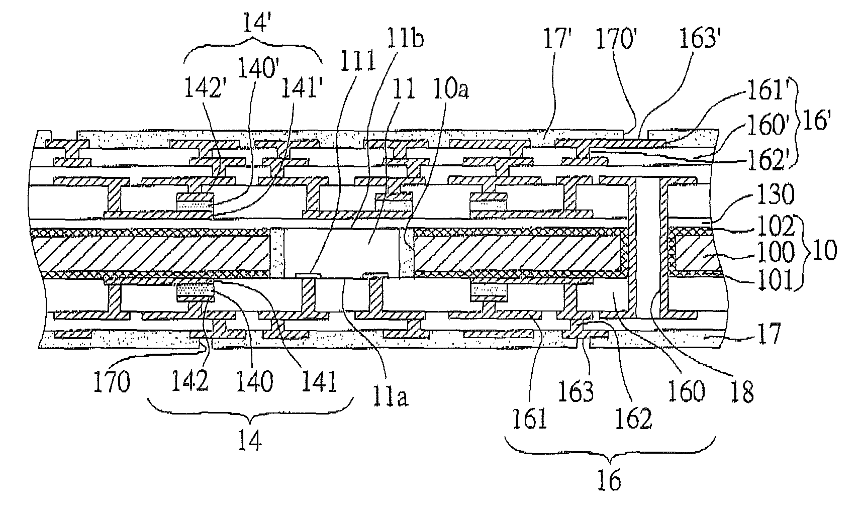
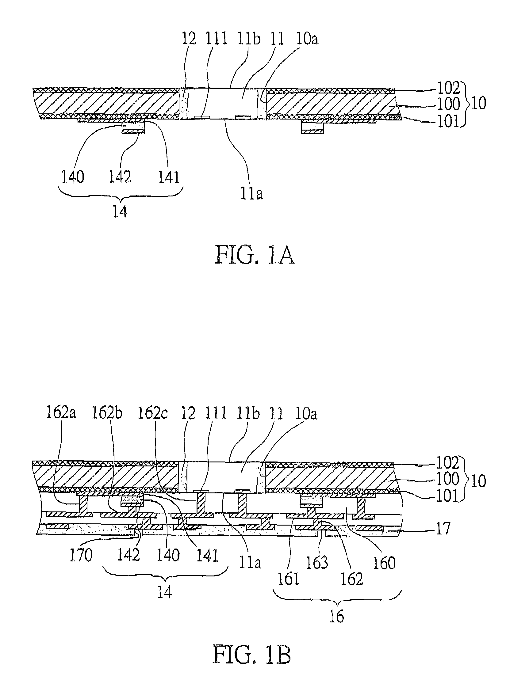
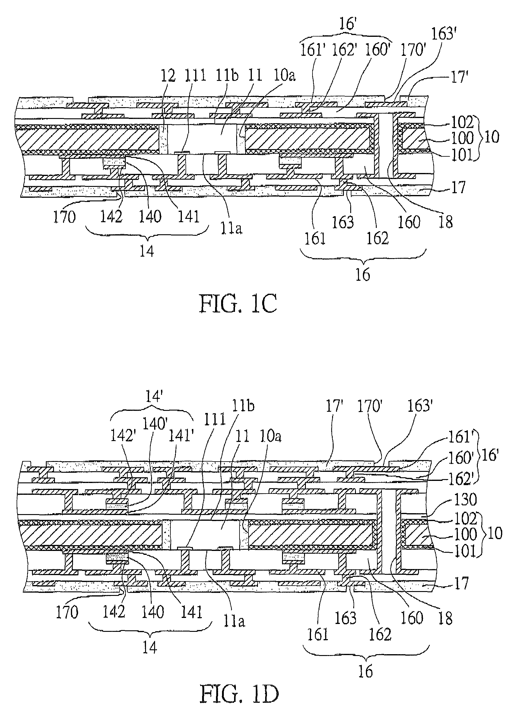
[0031]Referring to FIGS. 1A-1D, cross-sectional schematic views of a circuit board having electronic components integrated therein of the present invention are shown.
[0032]As shown in FIG. 1A, the circuit board having electronic components integrated therein comprises: a carrier board 10, at least one semiconductor chip 11 and a capacitor 14. The carrier board 10 is formed by respectively forming a first metallic oxide layer 101 and a second metallic oxide layer 102 on two sides of a metal layer 102. The metal layer 100 is made of aluminum which is oxidized to form the first metallic oxide layer 101 and second metallic oxide layer 102 on each side respectively for enhancing the rigidity of the carrier board 10. Moreover, the carrier board 10 has at least one through cavity 10a penetrating the carrier board 10. The semiconductor chip 11 is hold in the through cavity 10a of the carrier board 10. The semiconductor chip 11 has an active surface 11a with a plurality of electrode pads 111...
second embodiment
[0038]Referring to FIGS. 3A-3D, the difference between the second embodiment and the first embodiment is that the second embodiment further comprises a dielectric layer 131 disposed between the active surface 11a of the semiconductor chip 11 (together with the surface of the carrier board 10 at the same side) and the capacitors 14 for providing a better bonding between the capacitor 14 and the carrier board 10. Further referring to FIG. 4A-4D, in this embodiment, the dielectric layer 131 can replace the adhesive material to fill the gap between the through cavity 10a of the carrier board 10 and the semiconductor chip 11, so as to fix the semiconductor chip 11 in the through cavity 10a. Other main components in this embodiment can be referred to that of the first embodiment, therefore not given herein.
third embodiment
[0039]FIG. 5 shows a cross-sectional view of the circuit board having electronic components integrated therein of the third embodiment of the invention. The difference of this embodiment from the other embodiments is that in this embodiment the active surface 11a of the semiconductor chip 11 is at the same side with the second metallic oxide layer 102 of the carrier board 10. The circuit board structure comprises: a carrier board. 10 which is formed by respectively forming a first metallic oxide layer 101 and a second metallic oxide layer 102 on two sides of a metal layer 100, and, a through cavity 10a penetrating the carrier board; at least one semiconductor chip 11 having an active surface 11a with a plurality of electrode pads 111 thereon and an inactive surface 11b, hold in the through cavity 10a, wherein the active surface 11a of the semiconductor chip 11 is at the same side with the second metallic oxide layer 102; an adhesive material 12 filling the gap between the through ca...
PUM
 Abstract
Description
Claims
Application Information
 - R&D
- Intellectual Property
- Life Sciences
- Materials
- Tech Scout
- Unparalleled Data Quality
- Higher Quality Content
- 60% Fewer Hallucinations
Browse by: Latest US Patents, China's latest patents, Technical Efficacy Thesaurus, Application Domain, Technology Topic, Popular Technical Reports.
© 2025 PatSnap. All rights reserved.Legal|Privacy policy|Modern Slavery Act Transparency Statement|Sitemap|About US| Contact US: help@patsnap.com


