Method of forming LED-based light and resulting LED-based light

a technology of led-based light and led-based light, which is applied in the direction of semiconductor devices for light sources, lighting and heating apparatus, lighting support devices, etc., can solve the problems of affecting the performance of light sources, and the dispersion of light, so as to achieve a greater increase the ability to dissipate heat, and increase the surface area to width ratio

Active Publication Date: 2011-07-12
ILUMISYS
View PDF1011 Cites 185 Cited by
  • Summary
  • Abstract
  • Description
  • Claims
  • Application Information

AI Technical Summary

Benefits of technology

[0004]The present invention provides an LED-based replacement light including a heat sink having a high surface area to width ratio shaped from a flat sheet of thermally conductive material for replacing a conventional fluorescent light in a fluorescent fixture. Compared to an extruded heat sink of a conventional LED-based replacement light, shaping a heat sink from a sheet of highly thermally conductive material can result in a heat sink with a greater surface area to width ratio, and thus a greater ability to dissipate heat. Moreover, a shaped heat sink according to the present invention requires less material to produce and has a lower weight than an extruded heat sink. Further, a shaped heat sink according to the present invention can be produced less expensively than an extruded heat sink. In general, a method of forming an LED-based light according to the present invention includes providing the heat sink by shaping an elongate sheet of highly thermally conductive material to increase the surface area to width ratio thereof. The method also includes mounting a plurality of LEDs in thermally conductive relation with the heat sink along its length, and enclosing the LEDs within a light transmitting cover.

Problems solved by technology

Although conventional fluorescent bulbs have certain advantages over, for example, incandescent lights, they also pose certain disadvantages including, inter alia, disposal problems due to the presence of toxic materials within the glass tube.
However, LEDs produce heat during operation that is detrimental to their performance.

Method used


Image

  • Method of forming LED-based light and resulting LED-based light
  • Method of forming LED-based light and resulting LED-based light
  • Method of forming LED-based light and resulting LED-based light

Examples


Embodiment Construction

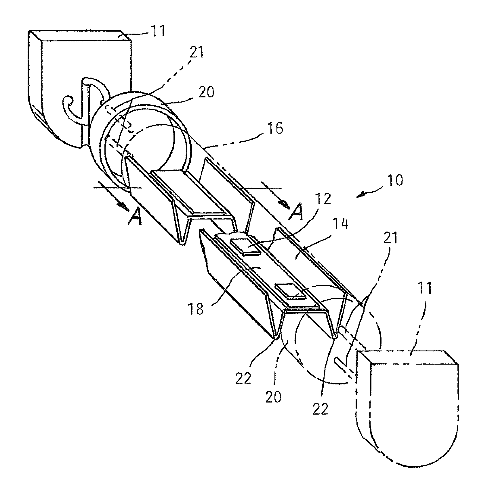
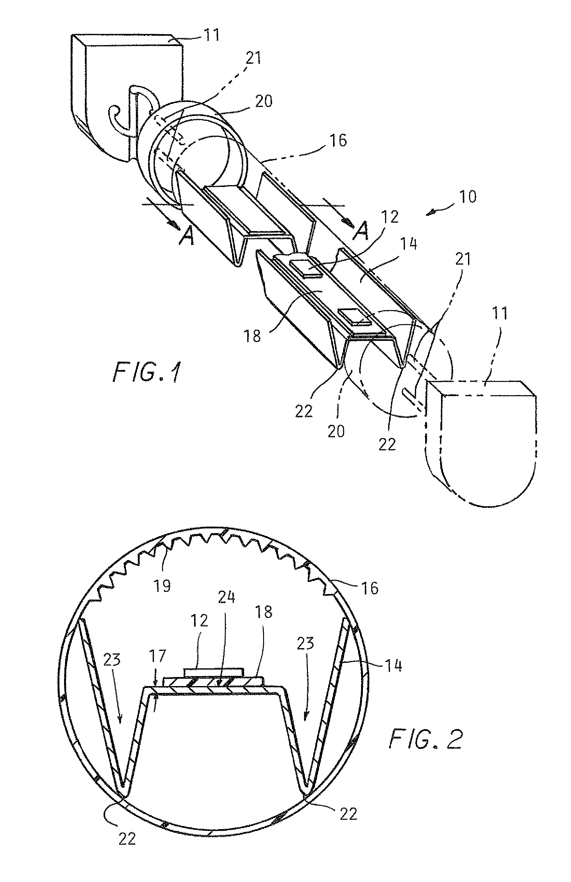
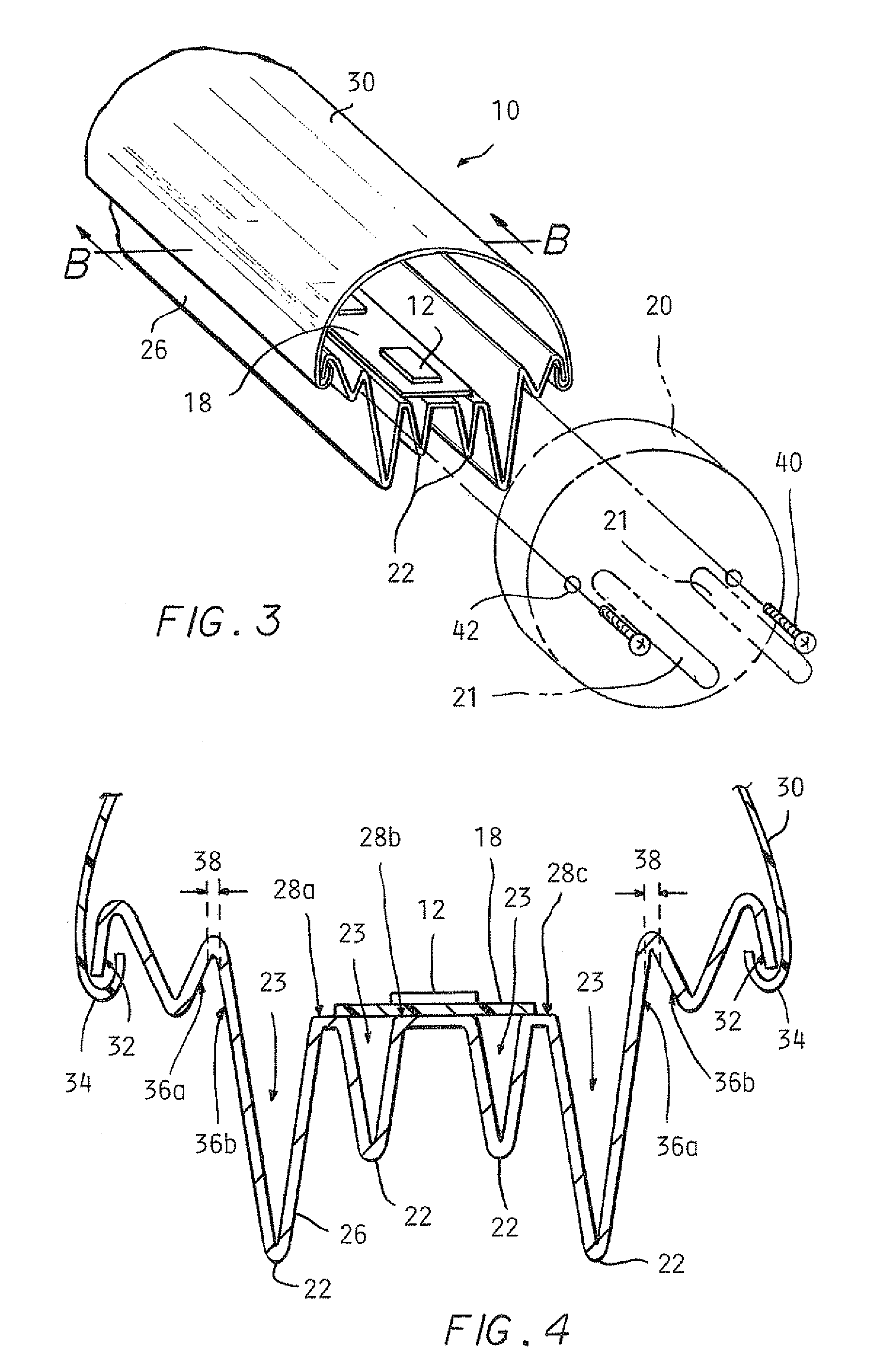
[0019]Embodiments of an LED-based replacement light 10 according to the present invention are illustrated in FIGS. 1-11. In an embodiment of the light 10 illustrated in FIG. 1, the LED-based replacement light 10 includes LEDs 12, an elongate heat sink 14 shaped from a sheet of highly thermally conductive material, an elongate translucent tube 16, a circuit board 18, and end caps 20 carrying bi-pin connectors 21. The LED-based replacement light 10 can be dimensioned for use in a conventional fluorescent fixture 11. For example, the LED-based replacement light 10 can be 48″ long with an approximately 1″ diameter.

[0020]The LEDs 12 are preferably high-power, white light emitting LEDs 12, such as surface-mount devices of a type available from Nichia. The term “high-power” means LEDs 12 with power ratings of 0.25 watts or more. Preferably, the LEDs 12 have power ratings of one watt or more. However, LEDs with other power ratings, e.g., 0.05 W, 0.10 W, or 0.25 W, can alternatively be used....


PUM


Abstract

A method of forming a LED-based light for replacing a conventional fluorescent bulb in a fluorescent light fixture includes shaping an elongate sheet of highly thermally conductive material to fashion a heat sink. Shaping the heat sink allows fashioning the heat sink to define cover and end cap attachment structures, surfaces for mounting LEDs at various angles, and a high surface area to width ratio for dissipating heat.

Description

TECHNICAL FIELD[0001]The present invention relates to a light emitting diode (LED) based light for replacing a conventional fluorescent light in a fluorescent light fixture.BACKGROUND[0002]Fluorescent tube lights are widely used in a variety of locations, such as schools and office buildings. Fluorescent tube lights include a gas-filled glass tube. Although conventional fluorescent bulbs have certain advantages over, for example, incandescent lights, they also pose certain disadvantages including, inter alia, disposal problems due to the presence of toxic materials within the glass tube.[0003]LED-based tube lights which can be used as one-for-one replacements for fluorescent tube lights have appeared in recent years. However, LEDs produce heat during operation that is detrimental to their performance. Some LED-based tube lights include heat sinks to dissipate the heat generated by the LEDs, and some of these heat sinks include projections for increasing the surface area of the heat ...

Claims


Application Information

Patent Timeline
Patent Type & Authority Patents(United States)
IPC IPC(8): F21V29/00F21V29/505
CPCF21K9/00F21K9/17F21V29/85F21V29/74F21Y2101/02F21Y2103/003F21V29/507F21V29/75F21K9/90F21K9/27F21Y2103/10F21Y2115/10
Inventor IVEY, JOHNSIMON, DAVID L
Owner ILUMISYS
Why Eureka
Try Eureka