Oscillator

a technology of oscillator and oscillator body, which is applied in the field of oscillator, can solve the problems of inability to achieve desired frequency change amount and frequency control function, limited capacitance variable range extension of variable capacitance element b>39/b>, and limited actuality in terms of development time and cost, so as to facilitate the control of variable amount of oscillator frequency and widen the variable range of oscillator frequency

Active Publication Date: 2011-07-26
SEIKO EPSON CORP
View PDF13 Cites 17 Cited by
  • Summary
  • Abstract
  • Description
  • Claims
  • Application Information

AI Technical Summary

Benefits of technology

[0015]An advantage of the present invention is to provide an inverter oscillator capable of easily controlling variable amount of oscillating frequency and having widened variable range of oscillating frequency.
[0016]An oscillator according to one aspect of the invention includes: an amplifier circuit including a semiconductor element having a first constant potential as a reference potential for a power supply voltage; a variable capacitance element; a piezoelectric resonator; and a capacitance circuit constituting a closed circuit with the piezoelectric resonator. The amplifier circuit and the variable capacitance element are connected in series to provide a series circuit. The capacitance circuit connects a plurality of capacitance elements in series. A connecting midpoint of the series connection is connected to a circuit for the first constant potential. Two connecting midpoints other than the connecting midpoint of the closed circuit are used as connecting points to connect the series circuit and the closed circuit in parallel.
[0017]According to the invention, the variable capacitance element is connected to the amplifier circuit in series and the oscillating loop portion is connected to the series circuit in parallel, thereby making it possible to allow parasitic capacitance to function as a bypass capacitor for the variable capacitance element and further to change frequency largely.
[0018]In this case, the variable capacitance element may be a voltage-controlled variable capacitance element, and a resistance for blocking of an alternating current may be connected between one voltage input terminal of the variable capacitance element and one connecting point, which is one of the two connecting points, to the closed circuit.
[0019]According to the invention, the variable capacitance element is connected to the amplifier circuit in series and the oscillating loop portion is connected to the series circuit in parallel, thereby making it possible to utilize parasitic capacitance positively, so that frequency can be changed with small change of control voltage.
[0020]In this case, the capacitance circuit may include a capacitance element constituted by a variable capacitance element.

Problems solved by technology

However, the extension of capacitance variable range of the variable capacitance element 39 is limited.
In particular, in the case in which the portions in the oscillator other than a piezoelectric resonator are made to be an integrated circuit (IC chip), the fabrication process of the IC chip must be drastically revised in order to make capacitance variable range of the variable capacitance element 39 optimal, which is, however, not realistic in actuality in the terms of development time and cost.
Further, even when the fabrication process of the IC chip is revised and optimal design is performed at simulation, adverse effects of parasitic capacitance occurring in parallel to the variable capacitance element 39 are large in the actual circuit, so there was a problem in that desired frequency change amount and frequency control function cannot be obtained.

Method used


Image

  • Oscillator
  • Oscillator
  • Oscillator

Examples


first embodiment

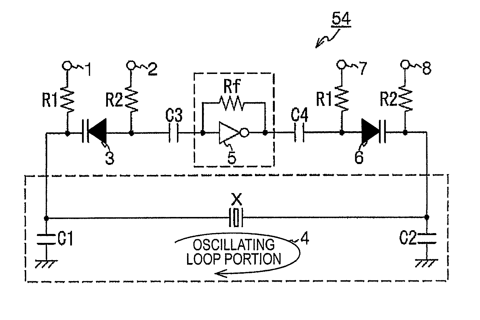
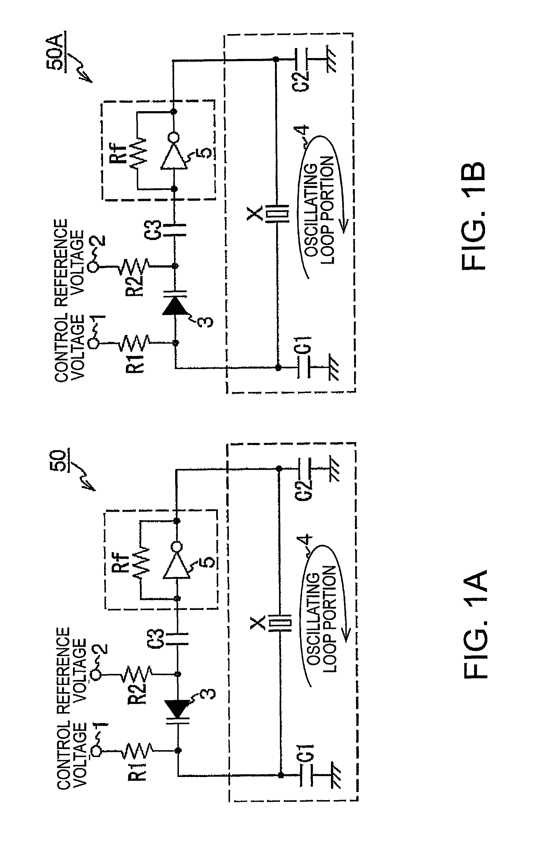
[0042]FIG. 1A and FIG. 1B each shows a view of circuit configuration of an oscillator according to the invention. An oscillator 50 according to the invention includes an amplifier circuit constituted by a semiconductor element using a ground potential as a first constant potential for a reference potential of power supply voltage, a quartz crystal resonator (piezoelectric resonator) X, a capacitance circuit constituting a closed circuit with the quartz crystal resonator, and a voltage-controlled variable capacitance element (varactor).

[0043]Further, the amplifier circuit is, for example, a single power supply type circuit and constituted as an inverter amplifier circuit, that includes: an inverter circuit 5 having a power supply terminal and, besides an input and output terminals, an earth terminal used for establishing connection to a circuit for grounding (circuit for the first constant potential); and a feedback resistance Rf.

[0044]The inverter amplifier circuit and the varactor ...

second embodiment

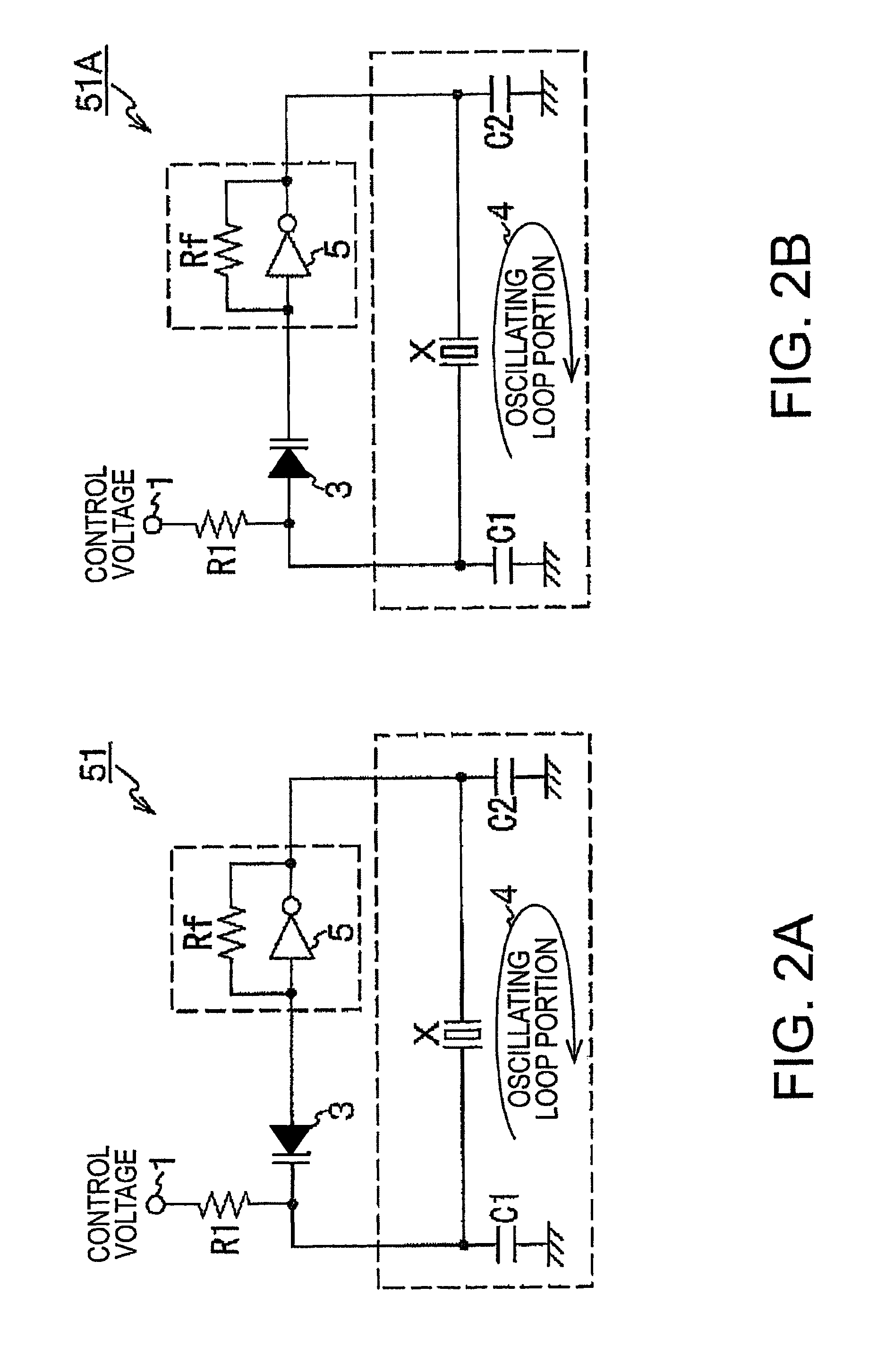
[0059]FIG. 2A and FIG. 2B each show a view of circuit configuration of an inverter oscillator according to the invention. In the following description, the components similar to those of the embodiment shown in FIG. 1A and FIG. 1B have the same reference symbols as the embodiment shown in FIG. 1A and FIG. 1B. In the inverter oscillator here, the capacitance element C3 for blocking of direct current shown in FIG. 1A and FIG. 1B is omitted, a capacitance circuit of the oscillating loop portion 4 is connected to a series circuit in parallel, in which one terminal of the varactor 3 is connected to the input side of the inverter circuit 5, and bias voltage at the input side or at the output side of the inverter circuit 5 is used as reference voltage to be applied to the varactor 3.

[0060]In other words, according to this embodiment of the invention shown in FIG. 2A, as compared with a circuit diagram of FIG. 1A, the capacitance element C3 for blocking of direct current is omitted and the ...

third embodiment

[0062]FIG. 3A and FIG. 3B each show a view of circuit configuration of an inverter oscillator according to the invention. In the following description, the components similar to those of the embodiment shown in FIG. 1A and FIG. 1B have the same reference symbols as the embodiment shown in FIG. 1A and FIG. 1B. The oscillator 52 here includes an amplifier circuit having a feedback resistance Rf and an inverter circuit 5, a quartz crystal resonator X connected between an input terminal and an output terminal of the inverter circuit 5, and an oscillating loop portion 4 including the quartz crystal resonator X.

[0063]Further, there are also provided the capacitance element C3 for blocking of direct current connected to the output side of the inverter circuit 5 and a varactor 3 connected to the capacitance element C3 for blocking of direct current in series.

[0064]Furthermore, the oscillator 52 has such a construction that a series circuit between the input side of the inverter circuit 5 an...


PUM


Abstract

An oscillator, includes an amplifier circuit including a semiconductor element having a first constant potential as reference potential for a power supply voltage, a variable capacitance element, a piezoelectric resonator, and a capacitance circuit constituting a closed circuit with the piezoelectric resonator. The amplifier circuit and the variable capacitance element are connected in series to provide a series circuit. The capacitance circuit connects the capacitance elements in a plurality of numbers in series. A connecting midpoint of the series connection is connected to a circuit for the first constant potential. Two connecting midpoints other than the midpoint of the closed circuit are used as connecting points to connect the series circuit and the closed circuit in parallel.

Description

BACKGROUND OF THE INVENTION[0001]1. Technical Field[0002]The present invention relates to an oscillator. In particular, the present invention relates to a circuit technique allowing variable range of oscillating frequency to be widely adjustable by using control voltage.[0003]2. Related Art[0004]Previously, there has been proposed an oscillator utilizing an inverter amplifier circuit so as to contribute to miniaturization of devices.[0005]Such oscillator is usually configured such that the oscillation of a piezoelectric resonator is amplified in a feedback loop. However, the oscillating frequency of the piezoelectric resonator is determined depending on capacitance of a capacitance element within an oscillating loop and therefore fixed. In view of this, there has been developed a VCO (voltage-controlled oscillator) as shown in FIG. 10.[0006]FIG. 10 is a circuit diagram of an inverter oscillator of related art disclosed in JP-7-273547. The inverter oscillator includes basically an in...

Claims


Application Information

Patent Timeline
Patent Type & Authority Patents(United States)
IPC IPC(8): H03B5/32
CPCH03B5/36
Inventor KIYOHARA, ATSUSHIYAMAMOTO, TAKEHIRO
Owner SEIKO EPSON CORP
Why Eureka
Try Eureka