
Delay compensated air/fuel control of an internal combustion engine of a vehicle

a technology of internal combustion engine and delay compensation, which is applied in the direction of electrical control, process and machine control, etc., can solve the problems of limiting the ability to properly regulate aggressive modulation of exhaust feed gas, low gain feedback control with sluggish response speed, and hindered closed loop fuel/air control using the uego sensor. the effect of response speed and accuracy

Active Publication Date: 2011-08-02
FORD GLOBAL TECH LLC
View PDF12 Cites 19 Cited by
  • Summary
  • Abstract
  • Description
  • Claims
  • Application Information

AI Technical Summary

Benefits of technology

The patent text describes a closed loop fuel control system for an engine that improves response speed and accuracy by using a linear or wide band continuous universal exhaust gas oxygen (UEGO) sensor instead of a switching type EGO sensor. However, the inventors have recognized that closed loop fuel / air control is still hindered by exhaust gas path dynamics, resulting in low gain feedback control with sluggish response speed. To address this issue, the system includes a delay compensation filter that compensates for the time delay in the fuel control by providing an error signal that is added to the desired fuel / air control signal. The system also includes a transient fuel control filter that adjusts the fuel / air control signal based on engine temperature to compensate for fuel puddle dynamics and increase the accuracy of the fuel control response. The technical effects of this system include increased response speed and accuracy of fuel control, improved emissions control device efficiency, and fuel economy.

Problems solved by technology

However, the inventors have recognized several potential issues with such an approach.
For example, closed loop fuel / air control using the UEGO sensor is still hindered by exhaust gas path dynamics.
Specifically, a relatively large time delay (time between a fuel change and the first indication of a measured fuel / air ratio response) exists that destabilizes the closed loop fuel / air control, resulting in low gain feedback control with sluggish response speed.
This limits the ability to properly regulate aggressive modulation of the exhaust feed gas which reduces catalyst efficiency.
Moreover, it compromises the ability to facilitate disturbance rejection, making the control approach more vulnerable to conditions of reduced drivability.

Method used


Image

  • Delay compensated air/fuel control of an internal combustion engine of a vehicle
  • Delay compensated air/fuel control of an internal combustion engine of a vehicle
  • Delay compensated air/fuel control of an internal combustion engine of a vehicle

Examples


Embodiment Construction

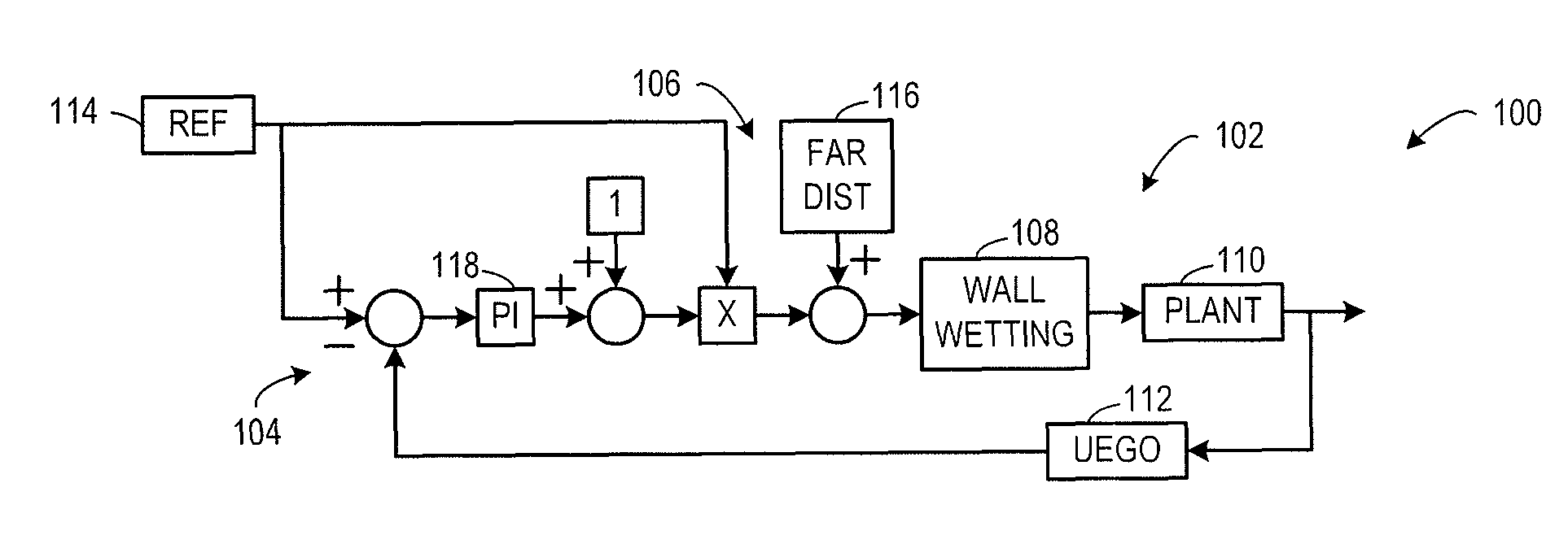
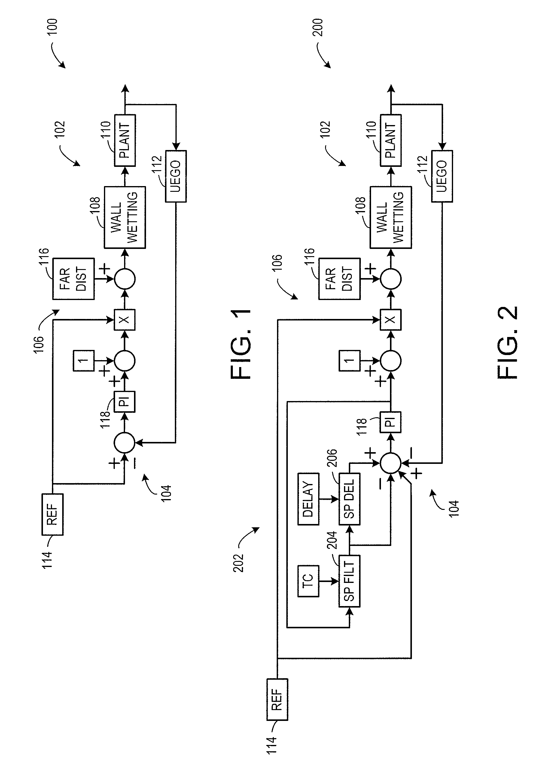
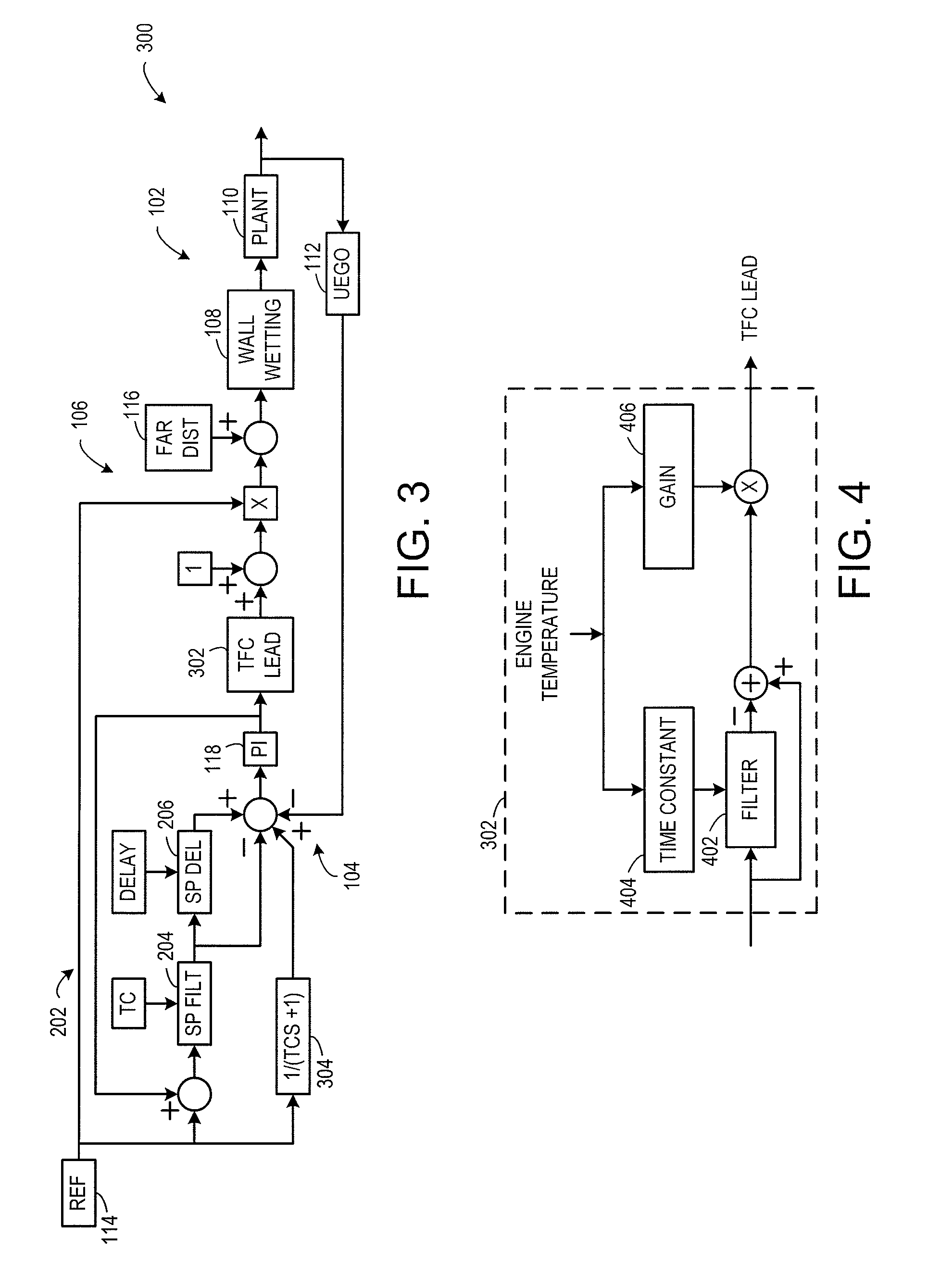
[0018]FIG. 1 shows a closed loop fuel control system 100 (referred to herein as “control system”) that operates based on feedback from a linear or universal exhaust gas oxygen (UEGO) sensor without compensating for a response delay of the UEGO sensor. The control system 100 varies fuel / air ratio based on operating conditions. A reference source 114 generates a desired signal at the input of control system 100 that is adjusted by various intermediate control blocks to provide a desired fuel control signal to a plant block 110 at the output of the control system. The desired fuel signal may be generated by the reference source based on the desired fuel / air ratio, which another part of the control system determines, to optimize emissions, fuel economy, and drivability. In these figures, the reference is assumed to be normalized fuel / air ratio, i.e. will be a value of 1 when the fuel and air inducted into the combustion cylinders has exactly enough fuel and oxygen to burn without any le...


PUM


Abstract

A fuel control approach that compensates for time delays to increase exhaust gas sensor feedback response speed.

Description

BACKGROUND AND SUMMARY[0001]Closed loop fuel / air control may be enhanced in terms of response speed and accuracy by using a linear or a wide band continuous universal exhaust gas oxygen (UEGO) sensor versus a switching type exhaust gas oxygen (EGO) sensor.[0002]However, the inventors have recognized several potential issues with such an approach. For example, closed loop fuel / air control using the UEGO sensor is still hindered by exhaust gas path dynamics. Specifically, a relatively large time delay (time between a fuel change and the first indication of a measured fuel / air ratio response) exists that destabilizes the closed loop fuel / air control, resulting in low gain feedback control with sluggish response speed. This limits the ability to properly regulate aggressive modulation of the exhaust feed gas which reduces catalyst efficiency. Moreover, it compromises the ability to facilitate disturbance rejection, making the control approach more vulnerable to conditions of reduced dri...

Claims


Application Information

Patent Timeline
Patent Type & Authority Patents(United States)
IPC IPC(8): F02D41/00G01M15/10
CPCF02D41/047F02D41/1456F02D41/1477F02D2041/141F02D2041/1431F02D2200/021
Inventor MAGNER, STEPHEN WILLIAMJANKOVIC, MRDJAN J.KERNS, JAMES MICHAELDONA, ALAN ROBERT
Owner FORD GLOBAL TECH LLC
Learn More