System and method for improving performance of coplanar waveguide bends at mm-wave frequencies

a coplanar waveguide and mm-wave frequency technology, applied in waveguides, waveguide type devices, cross-talk/noise/interference reduction, etc., can solve problems such as increased return losses, introduction of losses in transmission lines, and increased return losses

Inactive Publication Date: 2011-08-02
TOYOTA MOTOR CO LTD
View PDF152 Cites 9 Cited by
  • Summary
  • Abstract
  • Description
  • Claims
  • Application Information

AI Technical Summary

Benefits of technology

[0013]FIG. 1A is a schematic view of a prior art CPW bend that utilizes air-bridges for performance improvements;
[0014]FIG. 1B is a schematic view of a prior art chamfered CPW bend that utilizes air-bridges for performance improvements;
[0015]FIG. 2 is a schematic view of a prior art CPW bend that utilizes high-impedance transmission line sections under the air-bridges for performance improvements;

Problems solved by technology

One drawback is that transmission line bends introduce losses.
Return losses can be created due to capacitance and inductance being formed around the transmission line bends.
These influences significantly increase the return loss.
One drawback of a prior art CPW bend is that the two slots and the two ground planes on each side of the center conductor have different lengths.
The different lengths cause unwanted slot-line and parallel plate modes which tend to radiate and reduce the overall performance of the transmission line.
However, the inclusion of air-bridges 102 may add unwanted capacitance on the transmission lines which can further degrade the CPW performance.
Moreover, they require the fabrication of air-bridges which is complex.

Method used


Image

  • System and method for improving performance of coplanar waveguide bends at mm-wave frequencies
  • System and method for improving performance of coplanar waveguide bends at mm-wave frequencies
  • System and method for improving performance of coplanar waveguide bends at mm-wave frequencies

Examples


Embodiment Construction

[0021]Apparatus, systems and methods that implement the embodiments of the various features of the invention will now be described with reference to the drawings. The drawings and the associated descriptions are provided to illustrate some embodiments of the invention and not to limit the scope of the invention. Throughout the drawings, reference numbers are re-used to indicate correspondence between referenced elements and may not be described in detail for all drawing figures in which they appear.

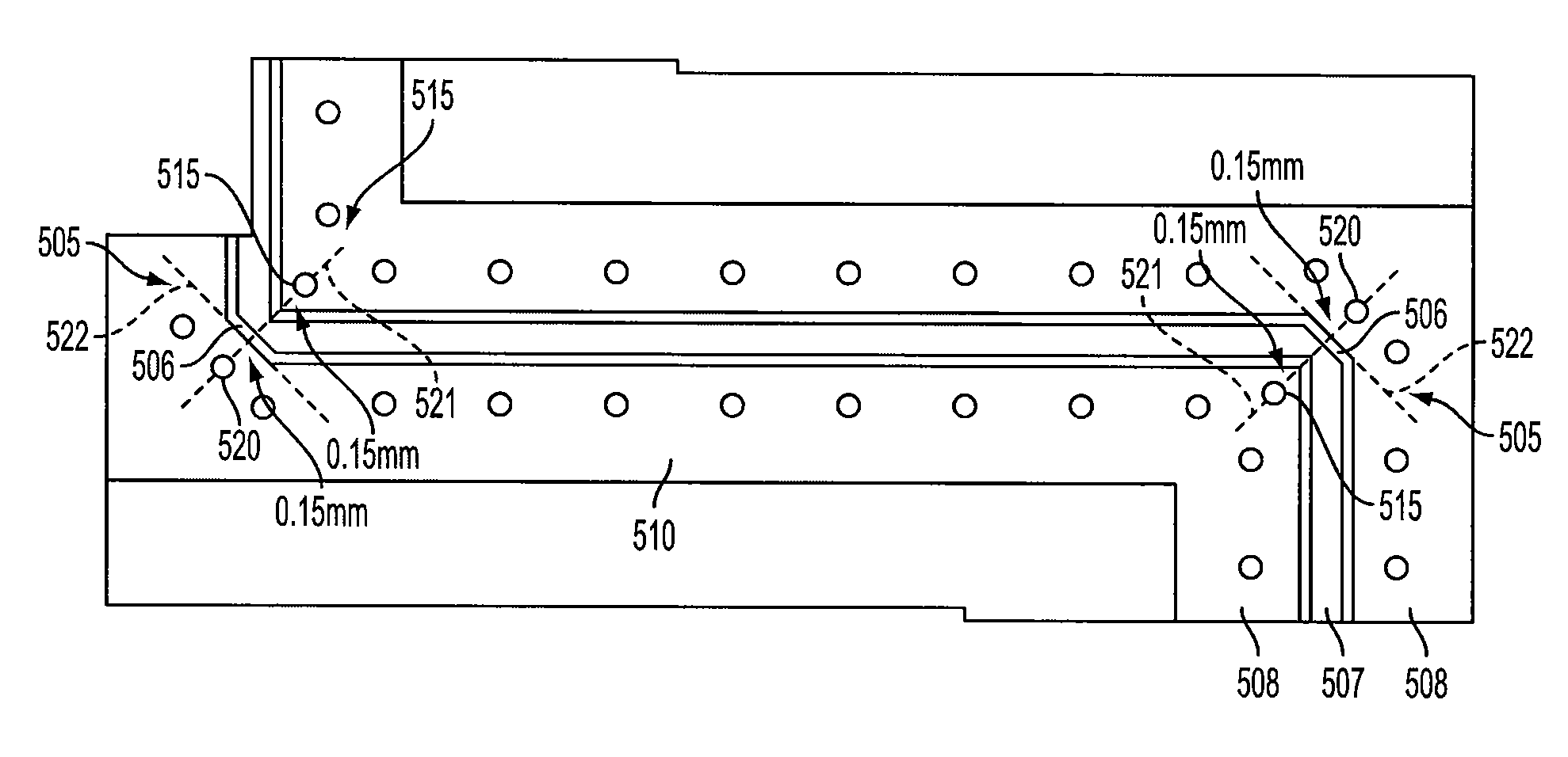
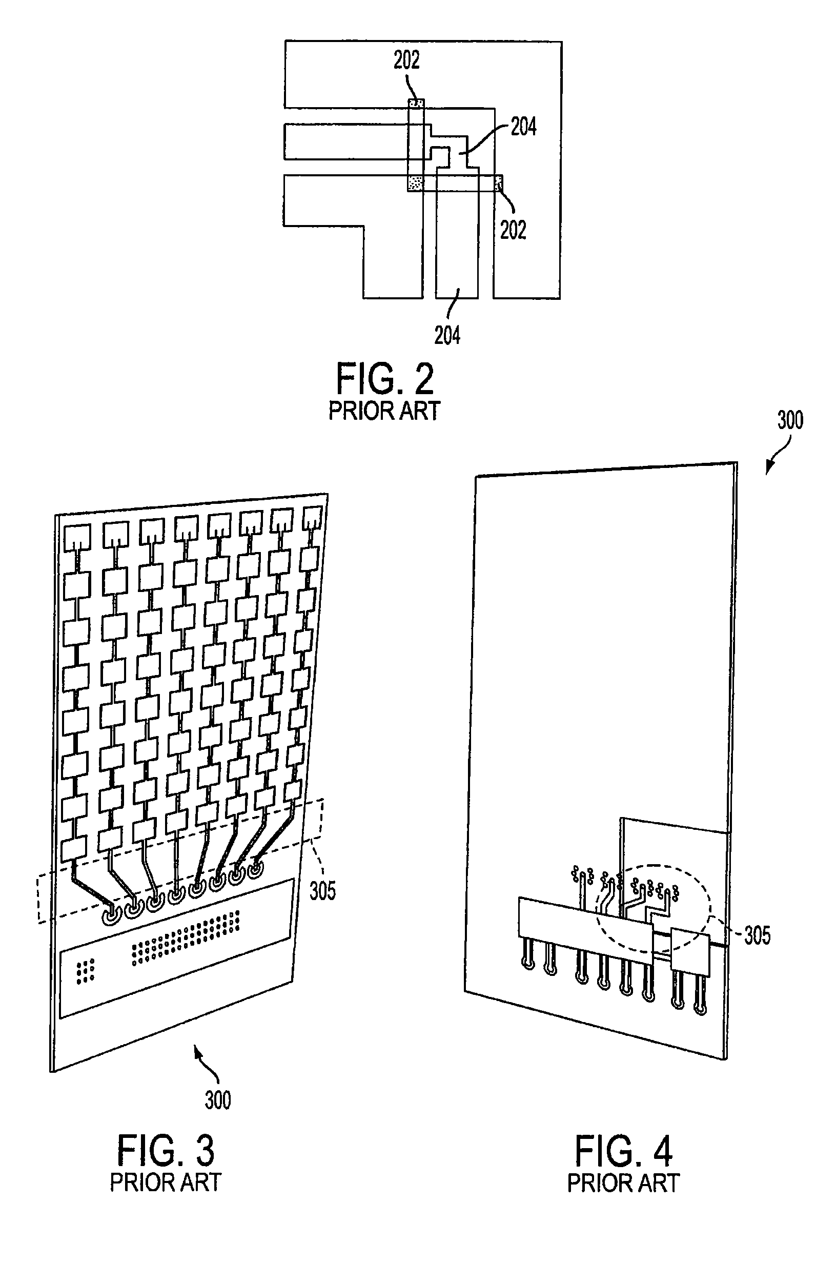
[0022]FIG. 3 is a schematic top view of a three-dimensional automotive radar RF front-end 300 having a plurality of CPW bends 305 according to an embodiment of the invention. FIG. 4 is a schematic bottom view of the three-dimensional automotive radar RF front-end 300 having a plurality of CPW bends 305 according to an embodiment of the invention. The plurality of CPW bends 305 achieve optimum performance by exploiting the capabilities provided by the use of a liquid crystal polymer (LCP) ...


PUM

PropertyMeasurementUnit
diameteraaaaaaaaaa
insertion lossaaaaaaaaaa
depthaaaaaaaaaa

Abstract

An apparatus including a liquid crystal polymer substrate having a top surface and a bottom surface, a coplanar waveguide formed on the top surface of the liquid crystal polymer substrate, the coplanar waveguide having a 90 degree bend with a mitered edge, an inner via positioned adjacent to an inner corner of the 90 degree bend, and an outer via positioned adjacent to the mitered edge of the 90 degree bend, the inner and outer vias positioned along a first plane that is perpendicular to a second plane defined by the mitered edge.

Description

BACKGROUND[0001]1. Field[0002]The invention relates to systems and methods for improving the performance of 90 degree coplanar waveguide (CPW) bends at mm-wave frequencies. More particularly, the CPW bends may be chamfered on the signal conductor and the ground plane and additional vias may be placed near the CPW bends.[0003]2. Background[0004]Microwave and mm-wave RF circuits may be integrated on a dielectric substrate with transmission lines (e.g., CPW) that feed the RF signals between the circuits. Such transmission lines often include bends that turn the direction of energy propagation (i.e., change the direction of field orientation) from one direction to another. A right angle transmission line bend, for example, turns the direction of energy propagation around 90 degrees. One drawback is that transmission line bends introduce losses.[0005]One type of loss, called a return loss, relates to the energy that is reflected back from the transmission line bend. Return losses can be ...

Claims


Application Information

Patent Timeline
Patent Type & Authority Patents(United States)
IPC IPC(8): H01P3/08
CPCH01P3/026H01P11/003H05K1/025H05K1/0219H05K2201/0141H05K2201/09272H05K2201/09618H01Q13/206
Inventor MARGOMENOS, ALEXANDROSRIDA, AMIN
Owner TOYOTA MOTOR CO LTD
Why Eureka
Try Eureka