Modular building frame

a building frame and modular technology, applied in the field of wood frame construction, can solve the problems of labor intensive process, skewed by lumber warping, and demands considerable skill from carpenters, and achieve the effects of low cost, cost competitiveness, and simple finishing of the building

Active Publication Date: 2011-08-09
ALLIED TUBE CONDUIT +1
View PDF49 Cites 15 Cited by
  • Summary
  • Abstract
  • Description
  • Claims
  • Application Information

AI Technical Summary

Benefits of technology

[0011]Accordingly, this invention provides an improved building frame, ideally suited for single story and multi-story buildings, that can be assembled rapidly at the building site by bolting together metal frame modules fabricated off site and attaching sheet metal elements that simplify the finishing of the building with exterior sheathing and interior wall board. This invention also provides an improved metal frame for a building having integral internal diamond bracing that enables the building to withstand the racking of severe earthquakes and high winds yet be cost competitive with comparable wood frame buildings. This invention provides an improved process for constructing a building frame that uses low cost standard frame modules for the majority of the frame and shorter or lower versions of the standard modules to adjust the length or height of the frame walls to accommodate any desired building size and joist height for floors between stories, to produce a building frame that is cost competitive with conventional wood frame buildings and substantially more resistant to damage from wind, fire and earthquakes. A further object of this invention is to provide an improved steel frame building having walls the same thickness as conventional wood frame buildings, so that standard door and window units can be used with normal appearance, but the building has the strength of a steel frame building and superior fire resistant benefits, while remaining cost-competitive with conventional wood frame buildings. This invention also provides an improved steel building frame that can be erected quickly in multiple stories using standard frame and anchor brackets. The invention provides a roof frame system using rectangular steel tubing that can accommodate virtually all desired roof designs, including hips and gables.
[0012]These and other features of the invention are attained in a building frame having side walls made of side wall frame modules bolted together along adjacent edges and end walls made of end wall frame modules bolted together along adjacent edges. The frame modules are constructed of rectangular steel tubing, typically 2″×2″, welded together in a welding jig to ensure exact 90° angles. The gauge or thickness of the tubing walls is selected for the desired strength. The wall frame modules, other than the window and door modules, have diagonal diamond bracing to provide rigidity against folding or wracking wind loads and forces experienced during earthquakes. The end walls are each bolted at their ends to ends of the side walls to form a peripheral wall of the building. Trusses for supporting a roof on the peripheral wall are bolted into pockets on top of the side walls between structural members at the top of the wall to secure the roof of the building on the peripheral wall, and structural tubing elements are connected diagonally to the trusses, coplanar with the top chords of those trusses, for supporting purlins adjacent the ridges of a hip roof. The peripheral wall is secured to a concrete foundation by attachment of the frame modules to special anchor brackets bolted to anchors set in a concrete foundation. The same anchor brackets can be arranged in pairs, oriented bottom-to-bottom, clamping between them the second story floor panels, to secure the frame wall of the second and subsequent stories to the supporting story below it and to establish high strength tensile load path between the foundation and the frame modules and the roof trusses. Light gauge metal elements are fastened on the inside and outside surfaces of the wall frame modules for speedy attachment of interior wall board and exterior siding. The roof is supported by longitudinally extending purlins that are attached to the trusses by the use of U-shaped brackets that are pre-welded to the top of the trusses. A canted eve strut is supported atop the side and / or end wall modules at the same angle as the top chord of the trusses to provide a flush support for the roof sheathing, parallel and in the same plane with the purlins. A high strength tensile load path is thus established through steel structure from the foundation through the frame to the roof for resisting high wing loading and shaking forces of earthquakes.

Problems solved by technology

It is a labor intensive process and demands considerable skill from the carpenters to produce a structure that has level floors, perfectly upright walls, square corners and parallel door and window openings.
Even when the building frame is constructed with the requisite care and skill, it can become skewed by warping of the lumber, especially modern low grade lumber produced on tree farms with hybrid fast-growth trees.
Although conventional wood frame buildings require very little equipment for construction, they have become quite costly to build.
The labor component of the cost is substantial, partly because of the wages that must be paid for the laborious process of constructing the frame, and partly because of the many government mandated extra costs such as workman's compensation and liability insurance, social security payments, medical insurance premiums, and the host of reports that must be made to the Government by employers.
The building can be made precisely and as strong as needed, but the cost is relatively high because of the costly materials and the skilled crew and expensive equipment need to assemble the building.
It is a construction technique generally considered unsuitable for single family residence building because the cost is high and the building walls are substantially thicker than those made using standard frame construction, so standard door and window units do not fit properly and must be modified with special trim that rarely produces the desired aesthetic appearance.
Earthquake damage is becoming a matter of increasing concern among homeowners because of the publicity given to damage and loss of life in recent earthquakes in the U.S. and abroad.
Earthquake preparedness stories and advice abound, but an underlying unresolved concern is that conventional wood frame homes in the past were not built to tolerate the effects of an earthquake, neither in its ultimate load-bearing capability nor its post-quake serviceability limits.
Modern building codes attempt to address this concern, but the measures they require merely add to the already high cost of a new home and may not always provide significantly improved resistance to earthquake damage, particularly with respect to after-quake serviceability.
Fire often follows an earthquake, as happened in the disastrous Kobe earthquake of 1994, and of course fire is a major threat to homes independent of earthquake.
When fire breaks out in a conventional home, the wood frame fuels the fire and reduces the chances of successfully extinguishing it before the entire structure is destroyed.
The other major catastrophic threat to homes is wind.
Wind loads on wood frame homes have destroyed many homes, primarily because the roof is usually attached so weakly to the walls that the combination of lift, exerted upward on the roof by the Bernoulli effect of the wind flowing over the roof, and pressure under the eves tending to lift the roof off the walls, wrenches the roof off the walls and allows the wind to carry the roof away like a big umbrella.
Without the roof, the walls of the-house collapse readily under the wind load, completing the total destruction of the house.
Termite and carpenter ant damage to wood frame homes is a major form of damage, costing many millions of dollars per year.
Although the damage done by insects is rarely life threatening, it is actually more extensive in total than the combined effects of wind and earthquake, and it is an ever-present danger in many parts of the country.

Method used


Image

  • Modular building frame
  • Modular building frame
  • Modular building frame

Examples


Embodiment Construction

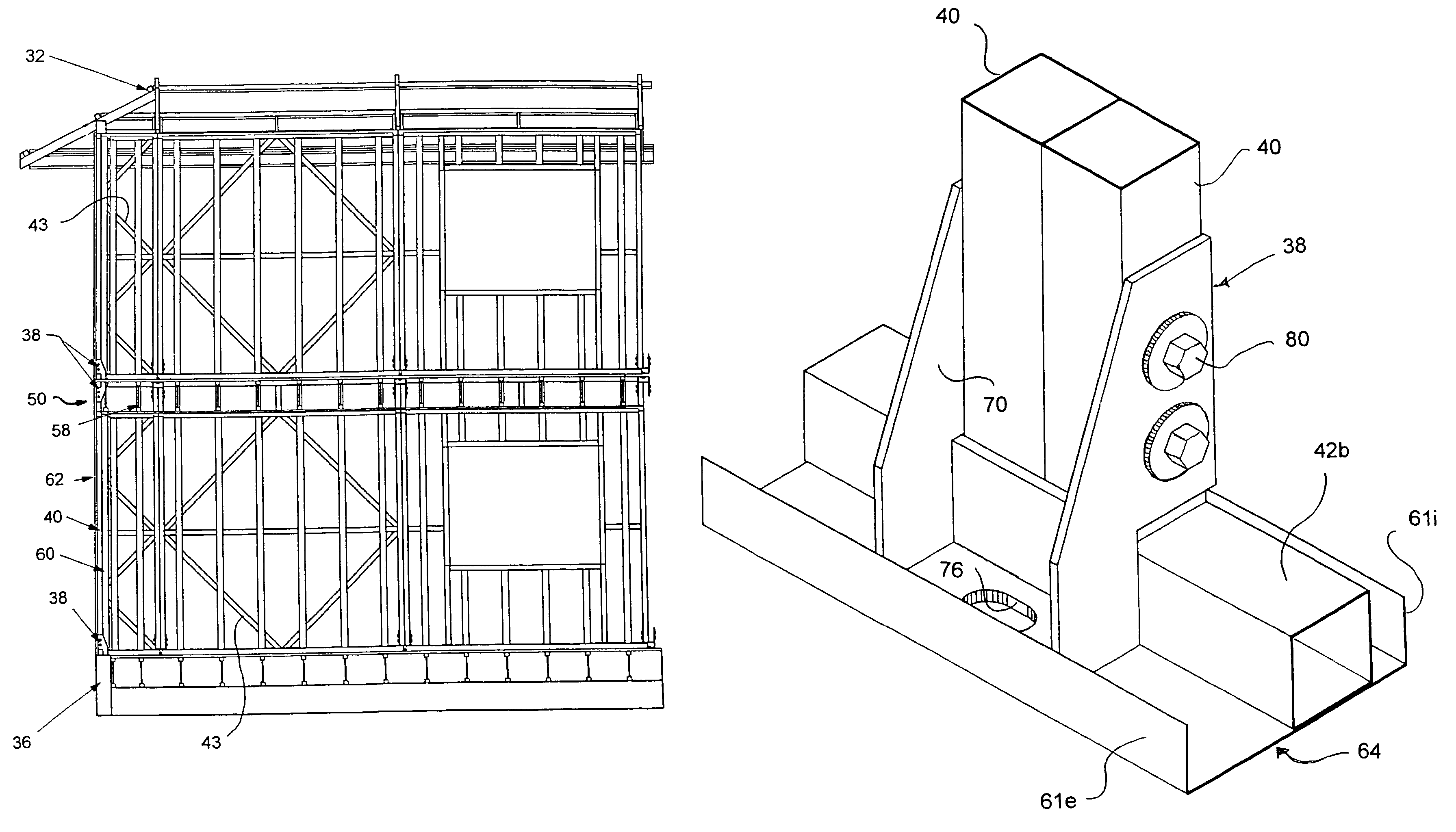
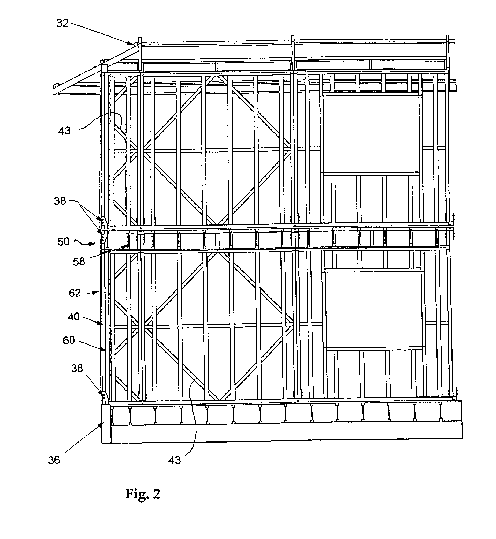
[0029]Turning now to the drawings, wherein like reference numerals designate identical or corresponding parts, and more particularly to FIGS. 1 and 2 thereof, one end corner of a two-story building frame 20 is shown having a peripheral wall (shown only partially) supporting a roof truss structure. The peripheral wall is made of two end walls 22 (only one of which is shown in FIG. 1) connected at their ends to ends of two side walls 26 (a portion of only one of which is shown in FIG. 1). The upper portions of the side walls 26 support opposite ends, of a plurality of main trusses 28 spaced apart along the side walls at regular intervals, and the end walls 22 support one end of a plurality of hip roof jack trusses 30, the other ends of which are supported on the main trusses 28 as will be described in more detail below. A plurality of purlins 32 are attached to the trusses 28 and 30 for supporting roof sheathing 34. The peripheral wall may be secured to a building foundation 36 by anc...


PUM


Abstract

A building frame resistant to earthquakes, gale-force wind loads, fire, insects and rot includes a peripheral frame wall constructed of rectangular steel tubing. Side wall frame modules and end wall modules bolted together along adjacent edges form the peripheral frame wall. Diagonal bracing is built into selected side and end wall modules as required for the desired degree of wind resistance. Trusses made of various size tube such as 2×3 inch rectangular steel tubing for supporting a roof, including a hip roof, on the peripheral wall, are assembled and welded in a welding shop and the prefabricated trusses and wall modules are trucked to the building site. Multiple stories may be erected and fastened together by anchor brackets arranged bottom-to-bottom above and below the second and higher floors. The building frame is secured to a foundation by attaching the anchor brackets to anchor bolts set in the foundation.

Description

[0001]This application is a division of U.S. patent application Ser. No. 09 / 468,981 filed on Dec. 21, 1999 and issued on Oct. 8, 2002 as U.S. Pat. No. 6,460,297, and also filed as PCT Application No. PCT / US00 / 35500 on Dec. 21, 2000 and published on Jun. 28, 2001 as Publication No. WO 01 / 46531.[0002]This invention relates to improved modular frames for buildings and buildings constructed from such frames, and more particularly to high quality buildings that can be erected quickly and at low cost from tubular steel modular frame units that are fabricated off site and trucked to the building site where they are bolted together into a building frame by a small work crew without the use of heavy equipment.BACKGROUND OF THE INVENTION[0003]Conventional building practice for residence housing and small commercial buildings relies primarily on wood frame construction in which the building frame is constructed on site from framing lumber cut to fit piece-by-piece individually. It is a labor i...

Claims


Application Information

Patent Timeline
Patent Type & Authority Patents(United States)
IPC IPC(8): E04H1/00E04B1/24E04C2/38
CPCE04B1/24E04C2/384E04B2001/2415E04B2001/2439E04B2001/2451E04B2001/2454E04B2001/2484E04B2001/249E04B2001/2496E04B1/08
Inventor BONDS, DELTON J.BRAMWELL, ERIC P.
Owner ALLIED TUBE CONDUIT
Why Eureka
Try Eureka