
Method for controlling exhaust gas purification system and exhaust gas purification system

a technology of exhaust gas purification system and exhaust gas, which is applied in the direction of electrical control, machines/engines, mechanical equipment, etc., can solve the problems of increasing increasing the cost of exhaust gas purification, so as to prevent deterioration of fuel efficiency and noise, reduce the temperature of exhaust gas, and reduce the effect of exhaust gas temperature rise efficiency

Active Publication Date: 2011-08-09
ISUZU MOTORS LTD
View PDF9 Cites 2 Cited by
  • Summary
  • Abstract
  • Description
  • Claims
  • Application Information

AI Technical Summary

Benefits of technology

The present invention provides a method for controlling an exhaust gas purification system for an internal combustion engine that can efficiently purify PM in the exhaust gas while increasing the temperature rise of the exhaust gas. The method includes a method for controlling an exhaust gas purification system that includes an oxidation catalyst and a diesel particulate filter device. The method includes a first exhaust gas temperature rise control to increase the engine speed of idling, followed by a second exhaust gas temperature rise control to decrease the engine speed of idling. The method also includes performing multi-injection in fuel injection control in the in-cylinder in the first exhaust gas temperature rise control, and performing post-injection in addition to the multi-injection control in the second exhaust gas temperature rise control. The method further includes performing regeneration control by using the temperature of the oxidation catalyst or the filter device as a determination temperature. The method can effectively purify PM in the exhaust gas while maintaining good fuel efficiency and reducing noise.

Problems solved by technology

Thus, oxidation reaction is not promoted, and oxidation of PM to regenerate a filter becomes difficult.
Therefore, accumulation of PM on the filter continues, and clogging of the filter progresses.
Thus, there emerges a problem of exhaust pressure rise caused by the clogging of the filter.
On the other hand, there is a problem of oil dilution that the HC is mixed with an engine oil (lubricating oil) by the post-injection and dilutes the engine oil.
However, because the engine speed of idling is increased to the same engine speed as that of the multi-injection even when the post-injection is performed in which the exhaust temperature has already been increased to the oxidation catalyst activation temperature by the multi-injection, there have been problems that the fuel efficiency deteriorates due to this idling up and that noise is generated.

Method used


Image

  • Method for controlling exhaust gas purification system and exhaust gas purification system
  • Method for controlling exhaust gas purification system and exhaust gas purification system
  • Method for controlling exhaust gas purification system and exhaust gas purification system

Examples


Embodiment Construction

[0035]Below, a method for controlling an exhaust gas purification system and the exhaust gas purification system in embodiments according to the present invention will be described by referring to the drawings.

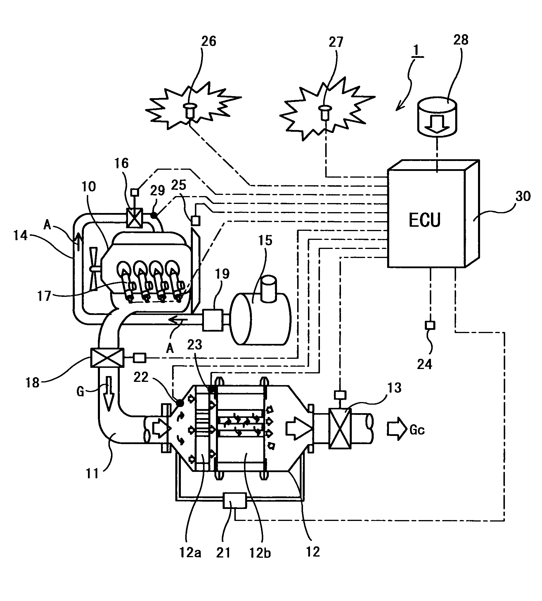
[0036]A configuration of an exhaust gas purification system 1 according to the present embodiment is shown in FIG. 1. The exhaust gas purification system 1 is configured to provide an exhaust gas purification device 12 in an exhaust passage 11 of a diesel engine (internal combustion engine) 10. The exhaust gas purification device 12 is one of continuous regeneration type DPF (diesel particulate filter) devices, and is configured to have an oxidation catalyst device 12a in an upstream side and a filter device with a catalyst 12b in a downstream side.

[0037]Further, an exhaust brake valve 18 is provided in an upstream side of the exhaust gas purification device 12, and an exhaust throttle valve 13 is provided in a downstream side thereof. Moreover, a positional relationship of th...


PUM


Abstract

In regeneration control, when the catalyst temperature index temperature (Tg2) using the temperature of the oxidation catalyst (12a) as an index is below a predetermined first determination temperature (Tc1), the engine speed of idling is brought to a predetermined first target engine speed (Nei1) which is higher than the engine speed of idling (Nei0) in the ordinary operation, and, further, multi-injection is carried out. On the other hand, when the catalyst temperature index temperature (Tg2) is the predetermined first determination temperature (Tc1) or above, the engine speed of idling is brought to a predetermined second target engine speed (Nei2), which is lower than the predetermined first target engine speed (Nei1) and is higher than the engine speed of idling (Nei0) in ordinary operation, and, further, post injection is carried out, followed by raising of the temperature of an exhaust gas flown into a DPF apparatus (12b) to a predetermined second determination temperature (Tc2). According to the above constitution, in the regeneration control of the DPF apparatus (12b) in an internal combustion engine (10), the regeneration can be forcibly carried out with high efficiency while enhancing the temperature rise efficiency of the exhaust gas, and, at the same time, excessive rise in the exhaust temperature, a deterioration in fuel consumption, and the occurrence of noise are suppressed.

Description

BACKGROUND OF THE INVENTION[0001]1. Field of the Invention[0002]The present invention relates to a method for controlling an exhaust gas purification system and the exhaust gas purification system for performing regeneration control including an exhaust gas temperature rise control accompanied with change of an engine speed of idling in order to recover a purification capacity of an exhaust gas purification device including a Diesel Particulate Filter (DPF) for purifying components in the exhaust gas in an internal combustion engine such as diesel engines.[0003]2. Background Art[0004]Regulations on an amount of the particulate matter (PM) exhausted from a diesel engine as well as NOx, CO, HC and the like have been tightened year by year. A technology has been developed wherein the PM is collected by a DPF to thereby reduce the PM amount exhausted to the outside. A continuous regeneration type DPF device carrying a catalyst is among them.[0005]In this continuous regeneration type DPF...

Claims


Application Information

Patent Timeline
Patent Type & Authority Patents(United States)
IPC IPC(8): F01N3/00F01N3/02
CPCF01N3/0235F01N13/0097F01N3/106F01N9/002F02D41/029F01N2430/085F01N2560/06F02D9/04F02D9/06F02D41/086F02D2200/0802F02D2200/0804F02M25/0727Y02T10/47F01N3/035F02M26/23F02D2200/604F02D41/405F02D41/402F02D41/0245F02D41/025F02D41/08Y02T10/12Y02T10/40
Inventor ONODERA, TAKAOHASEYAMA, TAKASHIWATANABE, YOSHINOBUIWASHITA, TAKUROHAGIO, KENJIMASHIKO, TATSUO
Owner ISUZU MOTORS LTD
Learn More