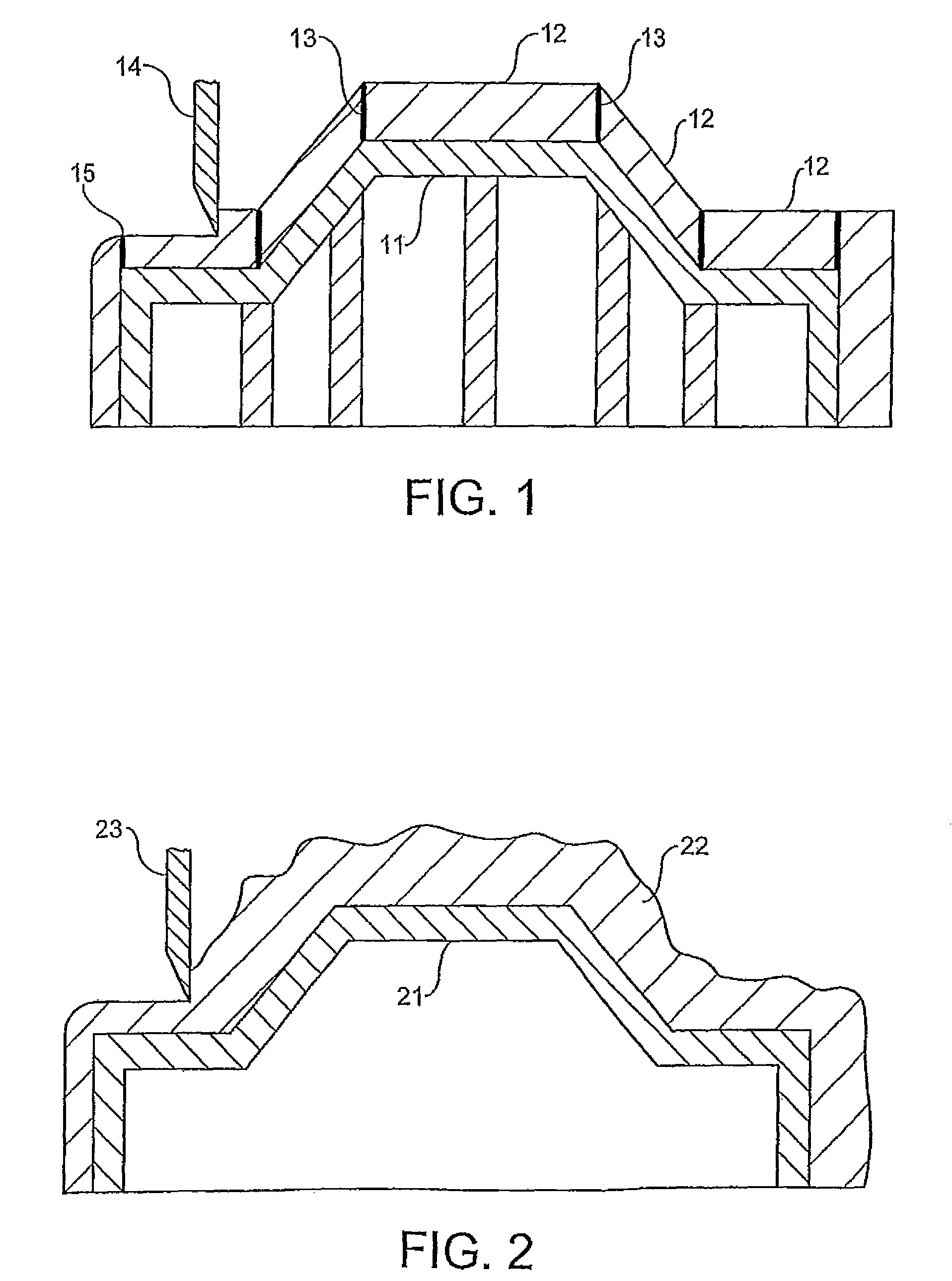
Method of making models

a model and model technology, applied in the direction of coatings, etc., can solve the problems of high cost and again labour-intensive approach, and achieve the effect of reducing the amount of syntactic material used, and reducing the dimensional change as the result of moisture absorption

Inactive Publication Date: 2011-08-09
HUNTSMAN ADVANCED MATERIALS AMERICAS INC
View PDF15 Cites 1 Cited by
  • Summary
  • Abstract
  • Description
  • Claims
  • Application Information

AI Technical Summary

Benefits of technology

[0010]The use of hybrid systems is very important, eg. a fast reacting component [eg. Michael Addition] combined with slower epoxy reacting system. This combination has been found extremely useful in controlling the heat produced during the reaction experienced in curable compositions containing high volume content of air either in the form of foam or microballoons.
[0050]In addition to the advantages mentioned above (namely lower and more uniform density, better machinability, smoother surface characteristics, and much greater overall efficiency), the modelling paste used in the present invention exhibits low linear shrinkage and can be used to produce large models that hold high tolerances. The finished article has excellent edge strength, cured shore hardness, flexural strength, heat deflection temperature and compressive strength, as well as a low thermal expansitivity.

Problems solved by technology

This approach, however, is labour intensive and requires precision operations, leading to high cost, and moreover results in a model which has bondlines at the surface, an appearance which is aesthetically undesirable.
However, this approach is again labour intensive, in that it involves hand application of the pliable solid patties to the honeycomb core.

Method used


Image

  • Method of making models

Examples


examples 2-5 (comparative)

[0064]The same general procedure of Example 1 is followed, except that the formulations noted in Table 2 below are used. The properties of the pastes so prepared show that these formulations are inferior for the preparation of a seamless modelling paste due to the poor dispensing characteristics as indicated by the low or high resistance to sag of the dispensed paste.

[0065]

TABLE 2Comparative formulations (all parts by weight unless indicated)(pts by weight)1) P36 / 2) LMQ070 / 3) LMQ070-1 / DM50071071-14) EE237Resin %6586.580.678.6LiquidMatrixHARDENERExpancel2.15.033.83.57551DEQCEL 502816None7.09.16Talcum10.5None3.13.28Calcium2.14.103.01.90StearateAdditives4.31.371.51.61PEINoneYesYesYesThixotropeIP232None1.500.50.94AerosilNone1.500.50.94PropertiesDensity0.55 / 0.440.48 / 0.450.50 / 0.500.47 / 0.50ConsistencyDry PasteWet PasteVery WetDryThixotropyNoToo MuchNot EnoughOKCracksNoYes > 25 mm(Little)(VeryLittle)Thickness>50 mm>50 mm>50 mm>50 mmHardness4537-3840-4238-41ShoreD(FULLYCURED)

example 6

[0066]This example is directed to the preparation of a suitable low density polyurethane modelling paste.

[0067]The formulation noted in Table 3 below is prepared in the same general manner as in Example 1.

[0068]The properties of the polyurethane paste so prepared show that this formulation is suitable for the preparation of a seamless modelling PU paste with fine cell structure and final density of 0.6 g / cm3 with excellent dispensing characteristics, in spite of the high microballoon content. Moreover, there is rapid set up of the high resistance to sag of the dispensed paste. Sag resistance is measured as in Example 1.

[0069]

%Polyol (Density 0.56)Triol Polyether polyol MW ~40055Castor oil27Molecular sieves1Mineral filler particle size ~5μ8.5Glass microballoons particle size ~80μ2.8Plastic microballoons particle size ~40μ3.5Colouring paste0.1DETDA1.0 to 1.5Aerosil1.0Antifoam agent0.1100.00Isocyanate (Density 0.65)Polymeric MDI NCO cont. 31.5%87.00Plastic coated microballoons12.5Liqui...

examples 7 and 8

[0070]

Lab ref:MC01-18-1MC01-28-2DescriptionWithout acrylicWith acrylicResinEpoxy resin6565Epoxy diluent104Pigments22Acrylate blend—7ATH filler1313Fumed silica22Thermoplastic44bubblesHardenerAmine adduct6565Non reactive diluent1010Fumed silica1.51.5Accelerator1—ATH filler1515Thermoplastic44bubblesHardness gainShore D 30 hrs1510Shore D 43 hrs3028Peak exothermEPS tub approx 300 g11286(° C.)

[0071]This examples illustrates the way in which the presence of an acrylic component serves to control the heat of reaction produced during curing (exotherm). As can be seen, the peak temperature in the formulation including the acrylic was 26 k lower 86° C.) then the peak temperature for the formulation without the acrylic (112° C.).


PUM

PropertyMeasurementUnit
densityaaaaaaaaaa
densityaaaaaaaaaa
densityaaaaaaaaaa

Abstract

A method of a seamless model free of bond lines. The method includes the sequential steps of providing a substructure having an exposed outer surface, applying a modelling paste to a structure support in the form of a continuous layer, curing the applied modelling paste, and machining the cured layer of modelling paste to the desired contour. The modelling paste a low density curable composition prepared from thixotropic epoxy or polyurethane containing microballoons.

Description

CROSS REFERENCES TO RELATED APPLICATIONS[0001]This application is a continuation application of U.S. patent application Ser. No. 10 / 498,692, pending, which is the National Phase of International Application PCT GB / 03 / 05652 filed Dec. 13, 2002 which designated the U.S. and was published in English and which claims priority to G.B. Pat. App. No. 0129986.6 filed Dec. 14, 2001. The noted applications are incorporated herein by reference.TECHNICAL FIELD[0002]The present invention is concerned with a method of making a model using a curable modelling paste and with models made using the method.BACKGROUND ART[0003]In the transport industries (for example, the automotive, rail and aerospace industries), it is common practice to produce large, dimensionally accurate master models. These models are used by engineers for the conceptual design of individual component parts of the final product.[0004]A known method involves a “building block” approach in which several boards are glued together t...

Claims


Application Information

Patent Timeline
Patent Type & Authority Patents(United States)
IPC IPC(8): C08J9/32B29C41/00C08G18/65C08G18/66C08G59/50C08K5/00C08K7/16C08L63/00C08L75/04
CPCB29C33/40B29C41/003C08G18/6696C08G59/5026C08J9/32B29C33/3892B29C2793/00B29K2105/007B29K2105/165C08J2363/00C08J2375/04C08K7/16
Inventor CLEAVER, MATTHEWARNOUX, DIDIER
Owner HUNTSMAN ADVANCED MATERIALS AMERICAS INC
Why Eureka
Try Eureka