[0011]The reduction in potential acoustic
acquisition rate, and ultimately frame rate, due to lateral sampling requirements, increased transmit resolution, and reduced round-trip sidelobe clutter, has led to many techniques being developed which seek to provide a true dynamic transmit focus and provide a better performance / frame rate tradeoff. The techniques developed generally fall into several classes, namely,
[0018]II. Multiple beam techniques, either transmit, receive, or both, seek to improve frame by reducing the number of transmit firings it takes to laterally sample the
region of interest. In the case of multiple simultaneous transmit beams, along with receive beams aligned along each transmit beam, less time is taken to sweep the region of interest to form the image for a given receive line density and thus, higher frame rate is achieved. However, the interference between the simultaneous transmit beams leads to increased acoustic clutter and degrades
image quality. Using multiple receive beams formed from the same transmit beam can also improve frame rates since less time is required to sweep the region of interest for a given receive line density. However, receive beams which are spatially displaced from the transmit beam center can lead to image
distortion, more so around the transmit focus, higher acoustic clutter, and results in spatial variance which is undesirable for high quality imaging. A way to mitigate this
distortion was described in U.S. Pat. No. 6,016,285, using two receive beams from each transmit firing and coherently (pre-detection) combining receive beams from two neighboring transmit firings, along with combining receive beams from the same firing as a way to re-center the receive beams along transmit firings. While eliminating
geometric distortion, line-to-line
gain variations are introduced, which if not removed through spatial filtering (which reduces
lateral resolution) lead to imaging artifacts. A multiple beam approach, Parallel
Beamforming using Synthetic Transmit Beams by T. Hergum, T. Bjastad, and H. Torp, 2004 IEEE International Ultrasonics, Ferroelectrics, and Frequency Control Joint 50th Anniversary Conference, pages 1401-1404, uses a weighted sum of multiple coherent receive beams from different transmit beams, forming an interpolated, or synthesized transmit beam, aligned along each receive beam. This addresses the lateral spatial sampling component of frame
rate reduction, however dynamic transmit focusing is not addressed. Therefore, use of multiple beams partially addresses the lateral spatial sampling component of frame
rate reduction; however, these classes of techniques have not addressed the transmit beam focusing aspect and as such, if increased transmit resolution is desired, multiple beams combined with some class of
compositing is required, with the advantages and disadvantages described previously.
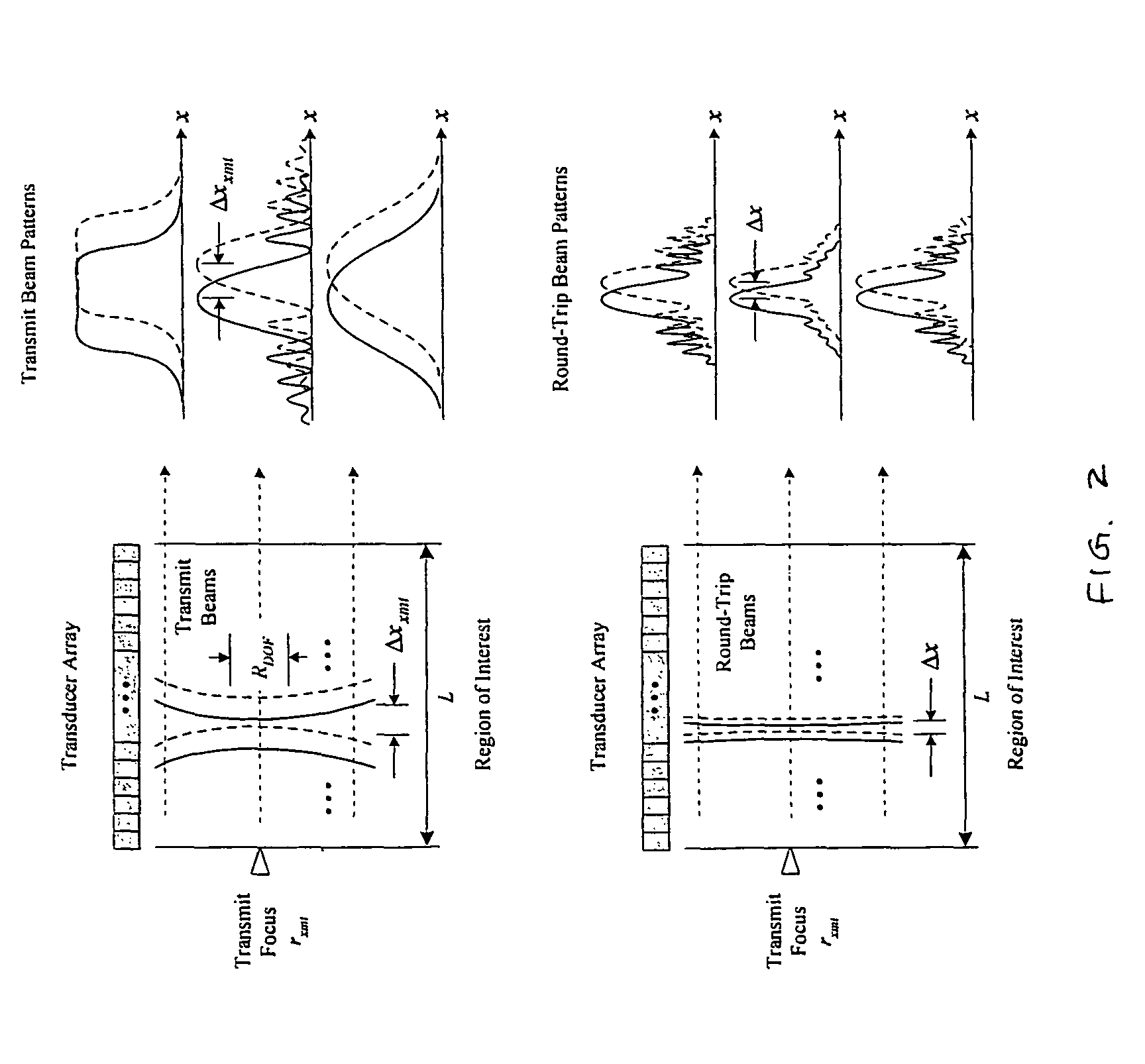
[0023]The present invention seeks to provide high quality imaging using a minimum of transmit firings by decoupling the Nyquist transmit and round-trip spatial sampling requirements, and at the same time maintaining a continuous transmit focus throughout the region of interest, which reduces or eliminates the need for transmit focus
compositing, i.e., sequential transmit focus, both of which dramatically improve the acoustic
acquisition rate. Reduction of the number of transmit firings becomes especially important for ultrasound systems which are battery powered in order to conserve energy and reduce
power consumption.
Elimination of transmit focus user controls is also a desirable feature, especially for
portable ultrasound systems given their compact
user interface. The invention works in linear or non-linear imaging
modes, works with standard 1-D and 2-D transducer arrays, can be extended to three spatial dimensions, i.e., 3-D imaging, is compatible with all scan formats, and is robust in presence of motion.
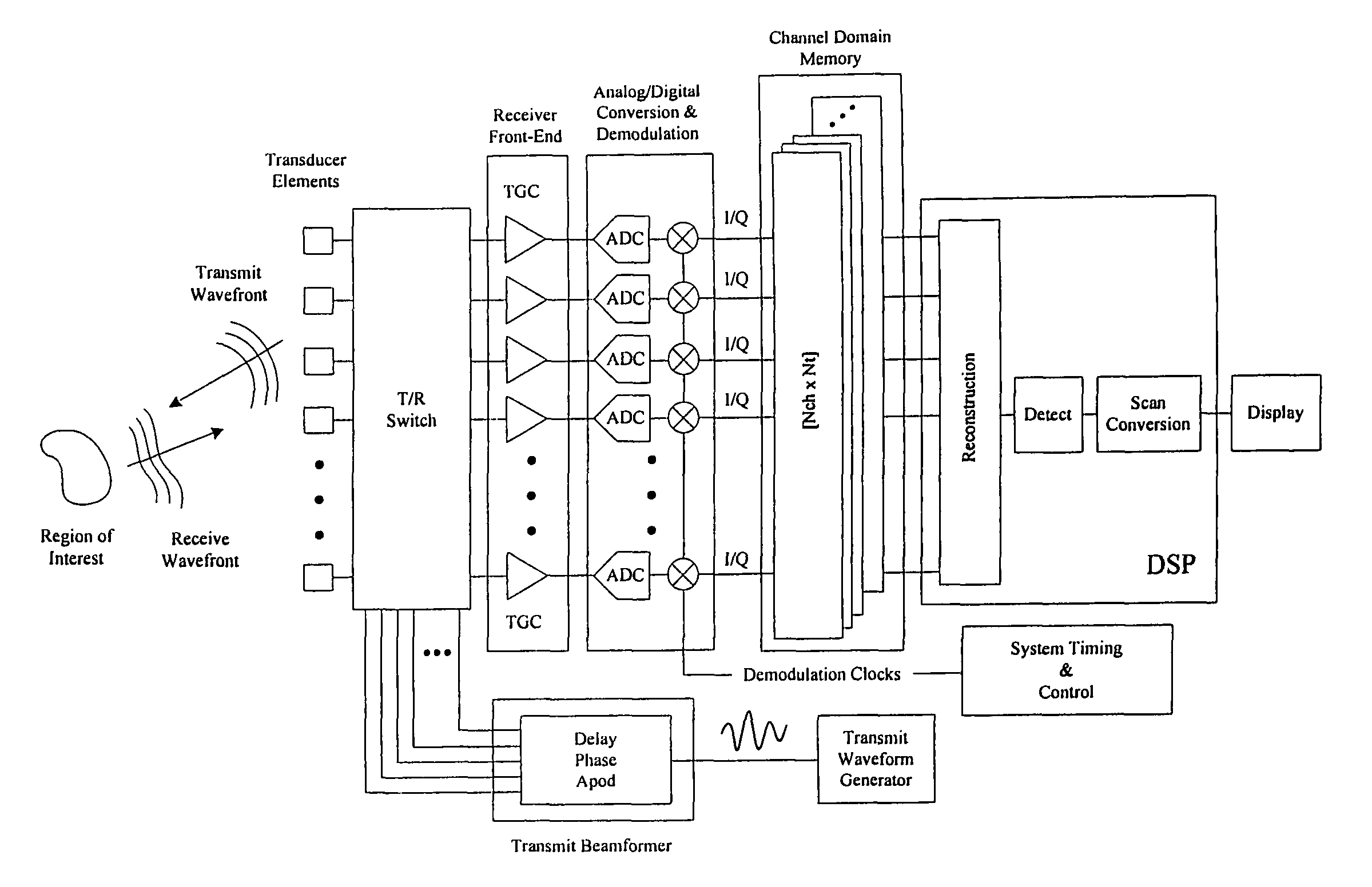
[0024]An aspect of the present invention is directed to an
ultrasound imaging method for achieving transmit and receive focusing at every echo location within a region of interest. The method comprises providing a probe that includes one or more transducer elements for transmitting and receiving ultrasound
waves; generating a sequence of spatially distinct transmit beams which differ in one or more of origin and angle; determining a transmit beam spacing substantially based upon a combination of actual and desired transmit beam characteristics, thereby achieving a faster echo acquisition rate compared to a transmit beam spacing based upon round-trip transmit-receive beam sampling requirements; storing coherent receive echo data, from two or more transmit beams of the spatially distinct transmit beams; combining coherent receive echo data from at least two or more transmit beams to achieve a substantially spatially invariant synthesized transmit focus at each echo location, i.e., to achieve transmit synthesis; and combining coherent receive echo data from each transmit firing to achieve dynamic receive focusing at each echo location.
[0027]In some embodiments, combining coherent receive echo data from at least two or more transmit beams to achieve transmit synthesis includes combining using one or more of
delay, phase, amplitude, and
convolution. Combining coherent receive echo data from at least two or more transmit beams to achieve transmit synthesis may be responsive to echo location, as well as to the spatial and temporal characteristics of the actual and / or desired transmit beam characteristics, which may include one or more non-linear components of the transmitted ultrasound
waves. The spatially distinct transmit beams may differ in one or more of
delay, phase,
apodization, amplitude, frequency, or coding. The spatially distinct transmit beams may have a single focus at a predetermined range, with an F-number
ranging from 0.5 to 10. Two or more of the spatially distinct transmit beams are fired simultaneously, or with a
time gap less than a round-trip
propagation time, for faster echo acquisition.
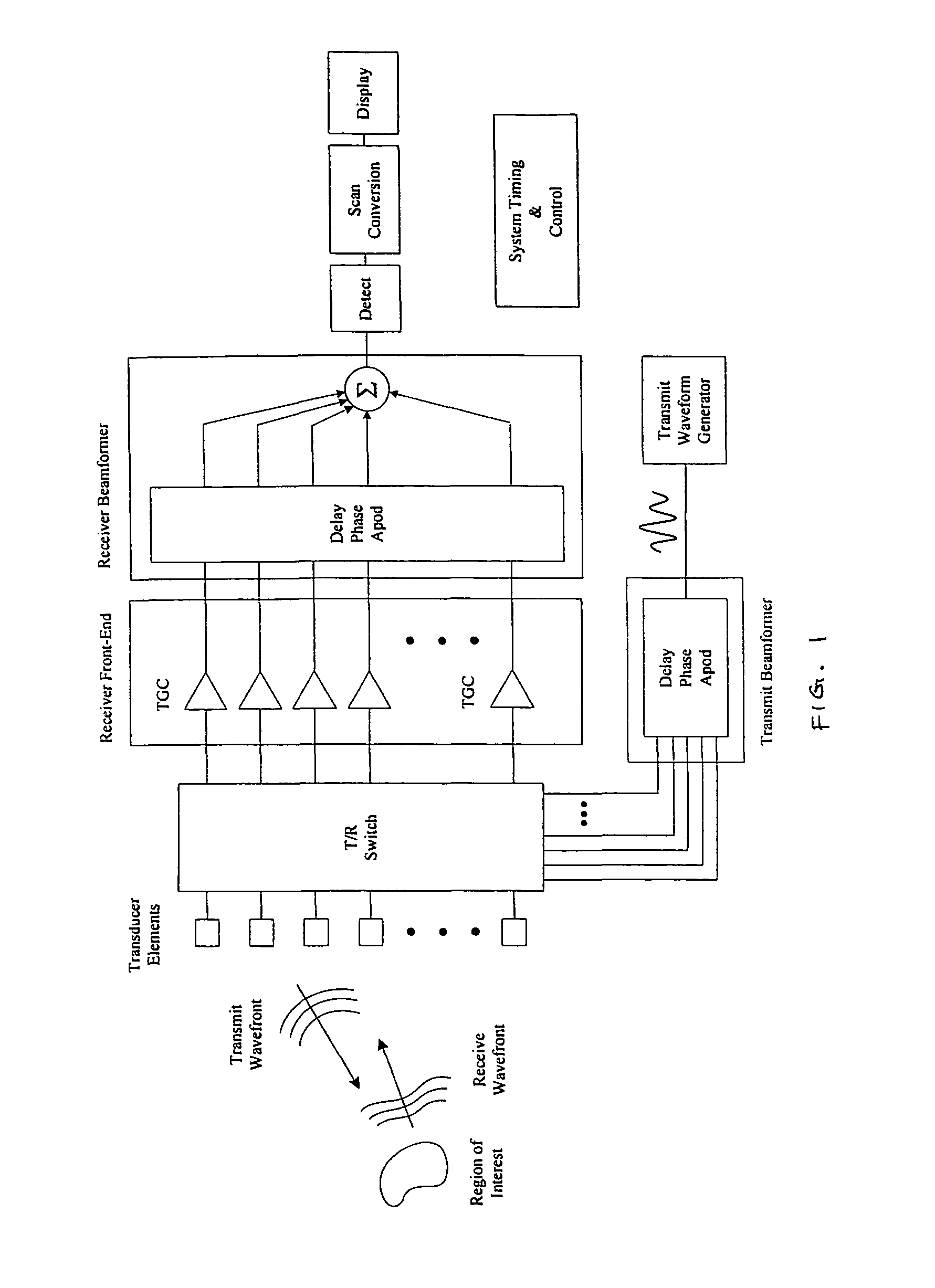
[0028]Another aspect of the invention is directed to an
ultrasound imaging system for achieving transmit and receive focusing at every echo location within a region of interest. The
system comprises a probe that includes one or more transducer elements for transmitting and receiving ultrasound waves; and a processor. The processor generates a sequence of spatially distinct transmit beams which differ in one or more of origin and angle; determines a transmit beam spacing substantially based upon a combination of actual and desired transmit beam characteristics, thereby achieving a faster echo acquisition rate compared to a transmit beam spacing based upon round-trip transmit-receive beam sampling requirements; stores coherent receive echo data, from two or more transmit beams of the spatially distinct transmit beams; combines coherent receive echo data from at least two or more transmit beams to achieve a substantially spatially invariant synthesized transmit focus at each echo location, i.e., to achieve transmit synthesis; and combines coherent receive echo data from each transmit firing to achieve dynamic receive focusing at each echo location.

