Instrumented component for use in an operating environment

a technology of operating environment and instrument, which is applied in the direction of liquid fuel engine components, mobile data collection devices, wireless architecture usage, etc., can solve the problems of difficult to obtain real-world operating environment data, designers and operators have very little information regarding the internal status of turbine engine components during operation, and superalloy materials cannot withstand extended exposure to the hot combustion gas of the current generation gas turbine engine withou

Inactive Publication Date: 2011-08-23
SIEMENS ENERGY INC
View PDF67 Cites 34 Cited by
  • Summary
  • Abstract
  • Description
  • Claims
  • Application Information

AI Technical Summary

Problems solved by technology

However, even superalloy materials are not able to withstand extended exposure to the hot combustion gas of a current generation gas turbine engine without some form of cooling and / or thermal insulation.
Such real world operating environment data is very difficult to obtain, particularly for components that move during the operation of the engine, such as the rotating blades of the turbine.
Despite the extreme sophistication of modern turbine engines, such as gas turbines for generating electrical power or aircraft engines for commercial and military use, designers and operators have very little information regarding the internal status of the turbine engine components during operation.
This is due to the harsh operating conditions, which have prevented the use of traditional sensors for collecting reliable information of critical engine components.
The lack of specific component information makes early failure detection very difficult, often with the consequence of catastrophic engine failure due to abrupt part failure.
This results in inefficient utilization, unnecessary downtime and an enormous increase in operating cost.
This approach is highly subjective and only allows for determining already severe situations with an engine.
It does not provide indications of impending damage or insight into the progression of events leading up to and causing engine damage due to component degradation or failure.
Instrumenting components using this technique is expensive, which is a barrier to instrumenting a large number of components within a single turbine.
Further, the wire leads and data transfer is frequently poor, which can result in costly repairs and flawed data analysis.
Using thermocouples for temperature measurements in the gas path of a turbine may be disadvantageous because it only provides feedback to an operator that a temperature change has occurred in the gas path.
This correlation is difficult and time consuming to derive to within a reasonable degree of certainty and needs to be done on an engine-by-engine basis taking into account turbine operation conditions.
When a temperature differential is measured, it is difficult, if not impossible, to predict what the problem is or where it is located.
Such diagnostic monitoring systems can only predict or estimate specific component conditions and do not collect data from or provide any analysis with respect to the actual condition of a specific component itself.
In this respect, conventional methods of predicting component failure for gas turbines and of scheduling maintenance have not been entirely accurate or optimized.
The traditional “duty cycle” used for predictive maintenance does not reflect real operational conditions, especially off-design operations.
For example, elevated temperatures and stresses within the turbine, and aggressive environmental conditions may cause excessive wear on components in the turbine beyond that predicted with the standard design duty cycle.
In either event, the standard design duty cycle model for predicting preventive maintenance does not reliably indicate the actual wear and tear experienced by gas turbine components.
None of these techniques provide accurate information with respect to the actual condition of a specific component or component coating, which may lead to unnecessary repair, replacement or maintenance being performed causing a significant increase in operating costs.

Method used


Image

  • Instrumented component for use in an operating environment
  • Instrumented component for use in an operating environment
  • Instrumented component for use in an operating environment

Examples


Embodiment Construction

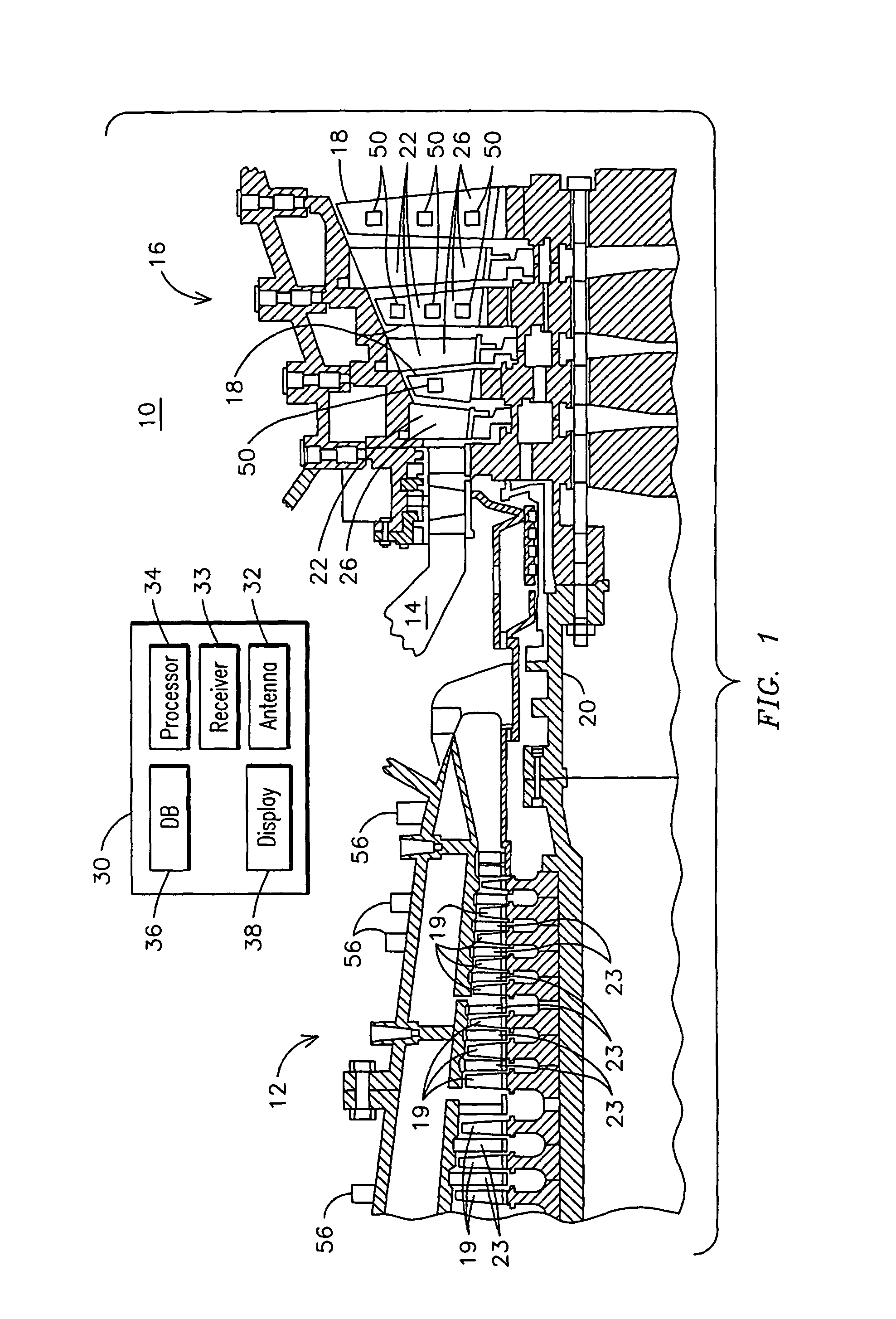
[0032]FIG. 1 illustrates an exemplary combustion turbine 10 such as a gas turbine used for generating electricity as will be recognized by those skilled in the art. Embodiments of the invention may be used with combustion turbine 10 or in numerous other operating environments and for various purposes as will be recognized by those skilled in the art. For example, embodiments may be used in aircraft engines, monitoring temperature and heat flux in boilers, heat exchangers and exhaust stacks; determining insulation performance and degradation; determining pipe fouling; and evaluating vibrating component health. Embodiments may be used in the automotive industry for monitoring combustion chamber conditions, rotating components such as crankshaft, cams, transmissions and differentials, and determining suspension and frame integrity for heavy-duty vehicles. Embodiments may also be used in measuring strain and heat flux in tanks, portable and other equipment operating in dessert, wet, and...


PUM

PropertyMeasurementUnit
temperaturesaaaaaaaaaa
operating temperaturesaaaaaaaaaa

Abstract

An instrumented component (18, 19) for use in various operating environments such as the hot gas path section of a combustion turbine engine (10). The component (18, 19) may have a substrate, a sensor (50, 204, 210) connected with the substrate for sensing a condition of the component (18, 19) within the casing during operation of the combustion turbine (10) and a connector (52, 202) attached to the substrate and in communication with the sensor (50, 204, 210) for routing a data signal from the sensor (50, 204, 210) to a termination location (53). The component (18, 19) may include a wireless telemetry device (54, 202) in communication with the connector (52, 202) for wirelessly transmitting the data signal outside the casing. A transceiver (56) may be located outside the casing for receiving the data signal and transmitting it to a processing module (30) for developing information with respect to a condition of the component (18, 19) or a coating (26) deposited on the component (18, 19).

Description

CROSS REFERENCE TO RELATED APPLICATIONS[0001]This application is a Continuation-In-Part of pending U.S. patent application Ser. No. 11 / 122,566 filed May 5, 2005, which claims the benefit of U.S. Provisional Patent Application No. 60 / 581,662 filed Jun. 21, 2004, both of which are specifically incorporated herein by reference in their entirety.FIELD OF THE INVENTION[0002]The present invention relates generally to monitoring operating environments and in particular to components enabled for transmitting data with respect to the condition of individual components within an operating environment such as a gas turbine engine.BACKGROUND OF THE INVENTION[0003]Gas combustion turbines are used for a variety of applications such as driving an electric generator in a power generating plant or propelling a ship or an aircraft. Firing temperatures in modern gas turbine engines continue to increase in response to the demand for higher efficiency engines. Superalloy materials have been developed to...

Claims


Application Information

Patent Timeline
Patent Type & Authority Patents(United States)
IPC IPC(8): G08C19/12
CPCF01D5/288F01D21/003F01D21/10F23R3/007G01D3/08H04Q9/00C23C28/321C23C28/3215C23C28/34C23C28/341C23C28/345C23C28/3455F01D17/02H04Q2209/50Y02T50/673F05D2230/90F05D2300/611H04Q2209/40Y02T50/60G08C17/02F01D5/12C04B35/00
Inventor MITCHELL, DAVID J.KULKARNI, ANAND A.SUBRAMANIAN, RAMESHROESCH, EDWARD R.
Owner SIEMENS ENERGY INC
Why Eureka
Try Eureka