

PDP filter and manufacturing method thereof
a technology of pdp filter and manufacturing method, which is applied in the field of pdp filter, can solve the problems of affecting the operation of wireless telephones or remote controllers, requiring much higher power consumption, and suffering from pdp, and achieves the effects of high pdp filter productivity, simple structure and mass production
Active Publication Date: 2011-08-23
LG CHEM LTD
View PDF15 Cites 6 Cited by
- Summary
- Abstract
- Description
- Claims
- Application Information
AI Technical Summary
Benefits of technology
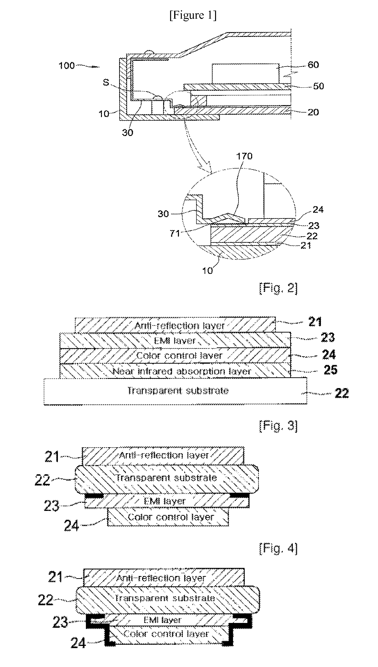
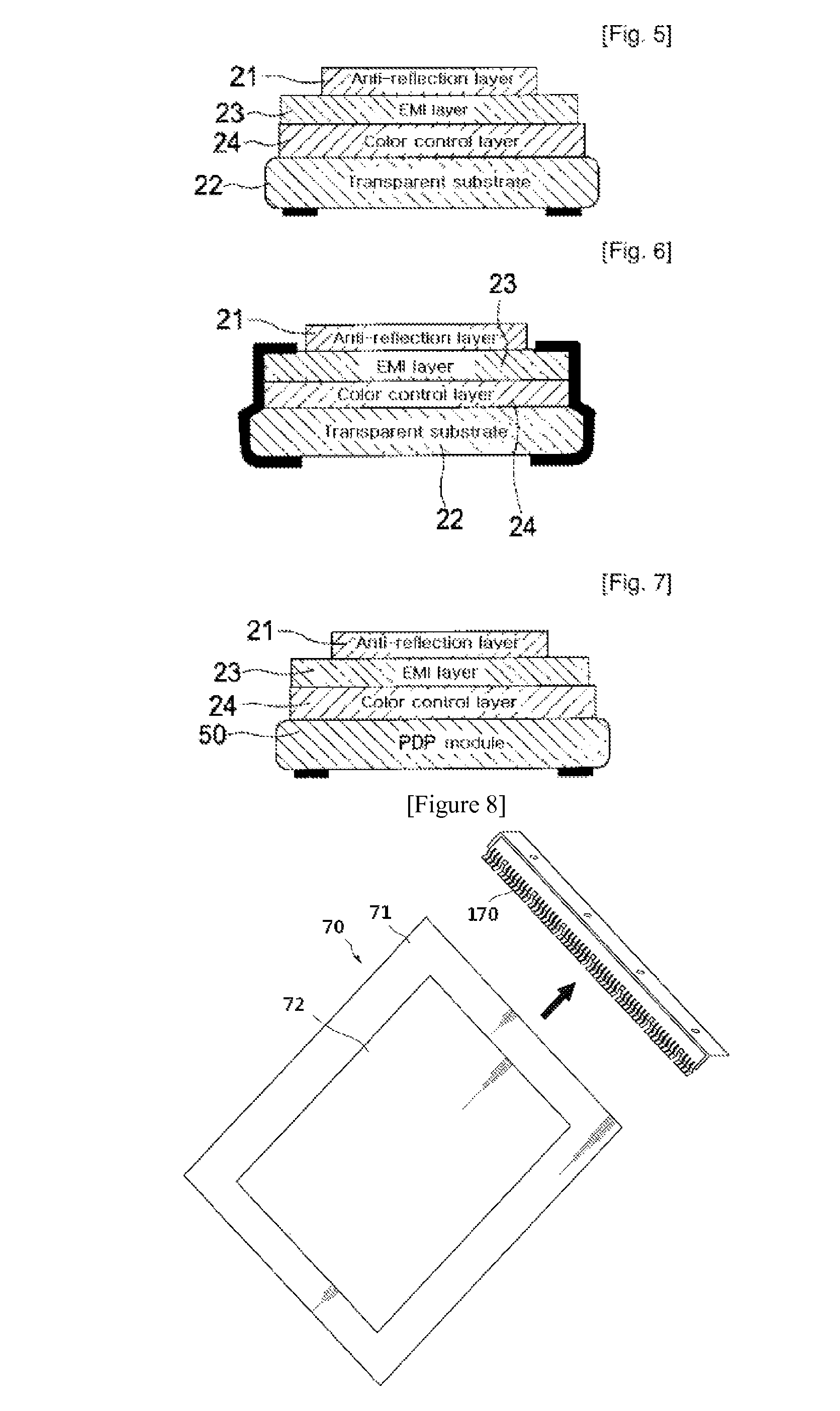
The present invention provides a PDP filter that can be formed into variously laminated structures and can be mass produced using a roll-to-roll manufacturing process. The filter includes a transparent conductive film type electromagnetic wave-shielding layer and one or more other functional layers. The invention also provides a method of manufacturing the PDP filter by integrating a functional film with the conductive film type electromagnetic wave-shielding layer using a compression roller. The invention also provides a PDP filter with a transparent substrate, a conductive film type electromagnetic wave-shielding layer, and a high-refractive transparent thin film layer, where at least two edge portions of the conductive film type electromagnetic wave-shielding layer are not exposed. The invention also provides a method of manufacturing the PDP filter by alternately laminating high-refractive transparent thin film layers and metal thin film layers on a transparent substrate, and providing a high-refractive transparent thin film layer on an uppermost surface of the alternately laminated layers. The invention also provides a PDP with the PDP filter, where the conductive film type electromagnetic wave-shielding layer does not need to be electrically grounded.
Problems solved by technology
However, the PDP suffers because it requires much higher power consumption than conventional CRT display devices, and thus electromagnetic waves and near infrared noise signals are more strongly emitted from the PDP set, compared to those of CRT display devices.
Further, the near infrared noise signals occurring from the PDP may negatively affect the operation of wireless telephones or remote controllers.
Although the PDP filter having a mesh type electromagnetic wave-shielding layer exhibits excellent electromagnetic wave-shielding effects, it reduces transparency and causes image distortion.
Further, since the mesh itself is expensive, a product price is undesirably increased.
However, such a manual process complicates manufacturing processes, and a roll-to-roll process (continuous manufacturing process) cannot be implemented, and thus mass production is impossible to realize, resulting in decreased productivity.
However, even though the laminated structure is formed using the transparent substrate in common, the conventional methods are disadvantageous because individual functional films should still be manufactured by separately forming the electromagnetic wave-shielding layer or anti-reflection layer on the transparent substrate.
Further, limitations are imposed on further decreasing the number of processes of separately manufacturing respective functional films or the number of laminated layers.
Method used
View moreImage
Smart ImageViewing Examples

Examples
example 1
[0159]Onto a transparent conductive film type electromagnetic wave-shielding film [visible light transmittance: 60˜65%, surface resistance: <1.8 Ω / □], available from Bekaert, an anti-reflection film (trade name: 7702UV), available from NOF Corp., Japan, was attached using a pressure sensitive adhesive. The integrated film thus manufactured was cut to a large size of 97 cm×56 cm, thus manufacturing a PDP filter in which the edge portions of the surface of the electromagnetic wave-shielding layer were not exposed.
Login to View More PUM
| Property | Measurement | Unit |
|---|---|---|
| visible light transmittance | aaaaa | aaaaa |
| refractive index | aaaaa | aaaaa |
| thick | aaaaa | aaaaa |
Abstract
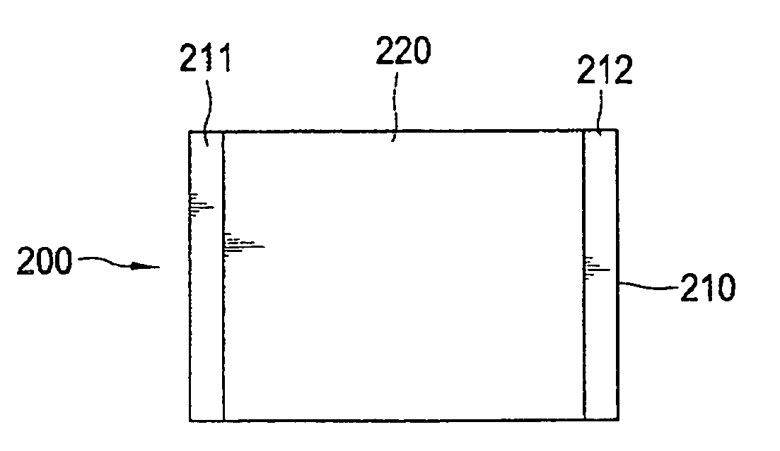
Disclosed herein is a PDP filter having a laminated structure of a transparent conductive film type electromagnetic wave-shielding layer and one or more other functional layers, in which at least two edge portions of the surface of the transparent conductive film type electromagnetic wave-shielding layer, which is in contact with the functional layer, are not exposed outside the laminated structure of the PDP filter.
Description
[0001]This application claims priority to International Application No. PCT / KR2006 / 000749 filed on Mar. 3, 2006, Korean Patent Application No. 10-2005-0018294 filed on Mar. 4, 2005 and Korean Patent Application No. 10-2005-0032392 filed Apr. 19, 2005, all which are incorporated by reference, as if fully set forth herein.TECHNICAL FIELD[0002]The present invention relates to a PDP filter and a method of manufacturing the same. More particularly, the present invention relates to a PDP filter using a transparent conductive film type electromagnetic wave-shielding layer, in which at least two edge portions of the surface of the transparent conductive film type electromagnetic wave-shielding layer, which is in contact with other functional layers, are not exposed outside the laminated structure of the PDP filter, and to a method of manufacturing such a PDP filter. In addition, the present invention relates to a PDP filter comprising a single optical film having an electromagnetic wave-shi...
Claims
Login to View More Application Information
Patent Timeline
 Patent Type & AuthorityPatents(United States)
IPC IPC(8): G02B1/10
CPCH01J9/205H01J11/10H01J11/44H05K9/0096G02B5/20Y10T156/10H01J2211/442H01J2211/446H01J2211/10G02B5/208H01J2211/444H01J2211/448H01J2217/49292
InventorLEE, DONG-WOOKLEE, YEON-KEUNHWANG, IN-SEOKKIM, SEUNG-WOOKPARK, SANG-HYUNKIM, JUNG-DOOCHOI, HYUN-SEOKLEE, SU-RIM
OwnerLG CHEM LTD