
Wavefront characterization and correction

a wavefront and wavefront technology, applied in the field of wavefront characterization and correction, can solve the problems of not disclosing any method or apparatus for correcting the wavefront of a beam, 999 patent does not disclose either method or apparatus, and perfect wavefront sources, etc., to achieve more ruggedness, computationally less intensive, and simple construction.

Active Publication Date: 2011-08-30
KESTREL CORP
View PDF5 Cites 9 Cited by
  • Summary
  • Abstract
  • Description
  • Claims
  • Application Information

AI Technical Summary

Benefits of technology

[0022]It is an object of the present invention to provide an adaptive optics system that, in comparison to existing adaptive optics systems, is simpler to construct, more rugged, computationally less intensive and hence faster, and cheaper.
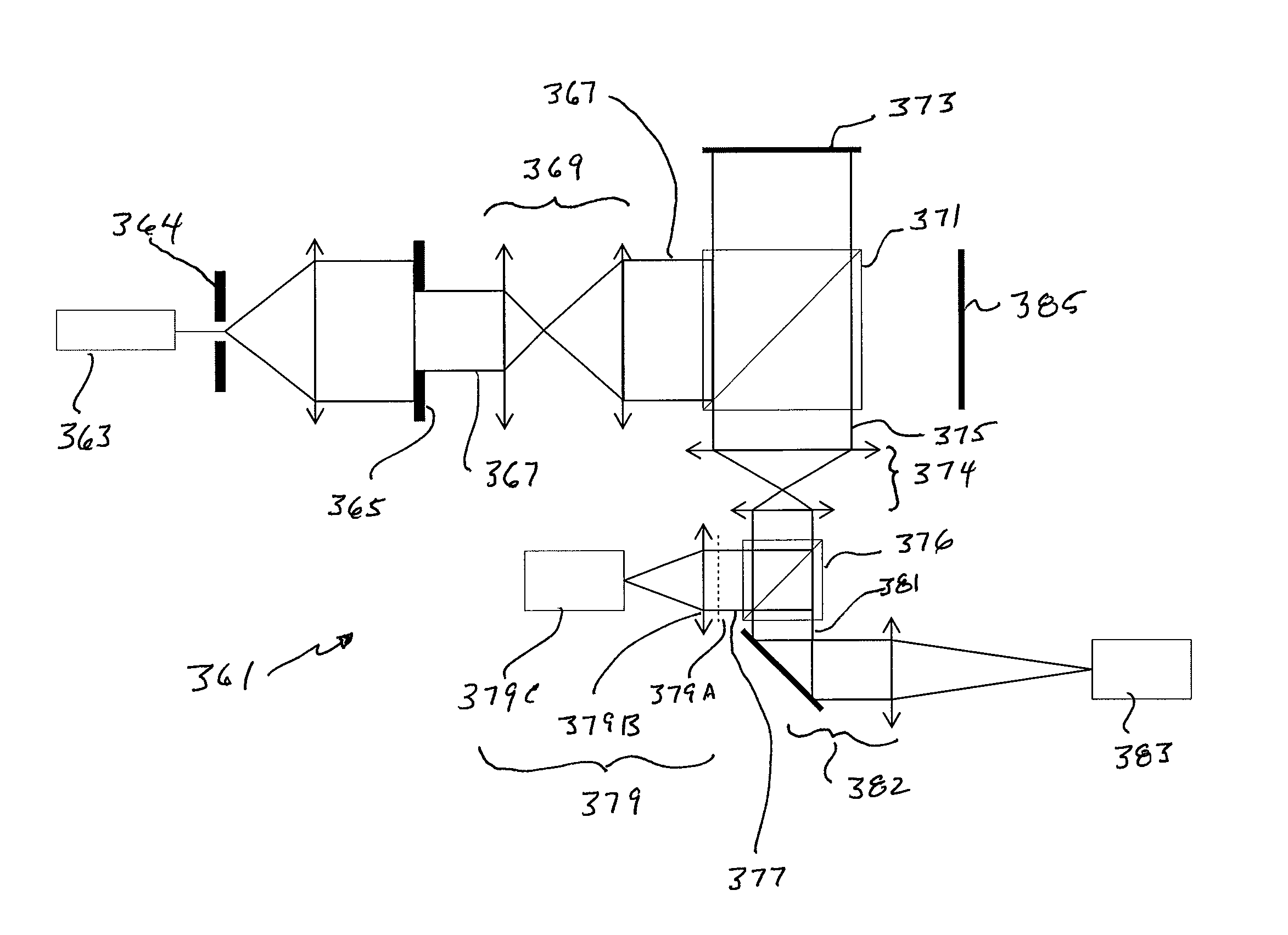
[0024]It is a further object of the present invention to, with the use of a distorted grating wavefront sensor, use a feature in the beam to be corrected to determine at least some of the characteristics of the associated wavefront. This removes the requirement for an artificially generated reference (sometimes referred to as a guide star) and allows a fundamental paradigm shift in the design of the wavefront sensing system. There is no known adaptive optics imaging systems constructed or proposed around any method other than the artificially generated reference method.

Problems solved by technology

While the '959 Patent discloses a sensor, it does not disclose any method or apparatus for correcting the wavefront of a beam.
The '999 Patent does not, however, disclose either a method or apparatus for: (1) correcting the output beam of a laser; or (2) correcting the image of an object prior to detecting such image.
The problem is finding a perfect wavefront source to measure.
However, it also has to be bright which severely limits the regions of the sky that can be observed (astronomical telescopes typically have a very small field of view and so the chances of a bright star being within the field of view of the object which an astronomer wants to observe is very small).
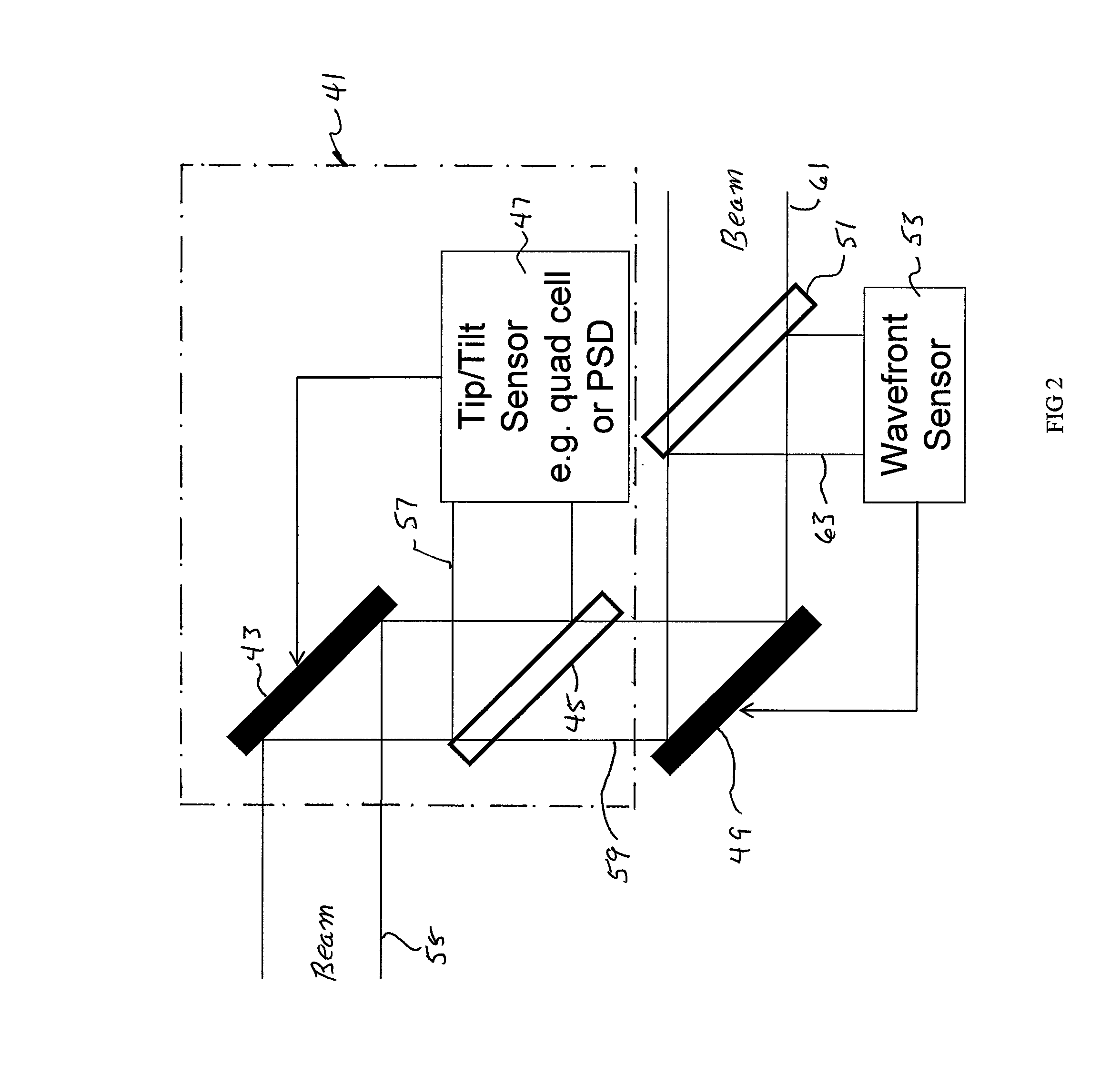
The foregoing adaptive optics systems have the following disadvantages: (a) they require a routine for mathematically reconstructing the measured wavefront, which routine is computationally intensive; (b) they require a routine for determining the slope (or the curvature) of the reconstructed wavefront, which routine is also computationally intensive; (c) when used for imaging they require the use of an artificially generated reference (e.g., a guide star); and (d) they require a separate data collection / control loop for a tip / tilt correction device.

Method used


Image

  • Wavefront characterization and correction
  • Wavefront characterization and correction
  • Wavefront characterization and correction

Examples


Embodiment Construction

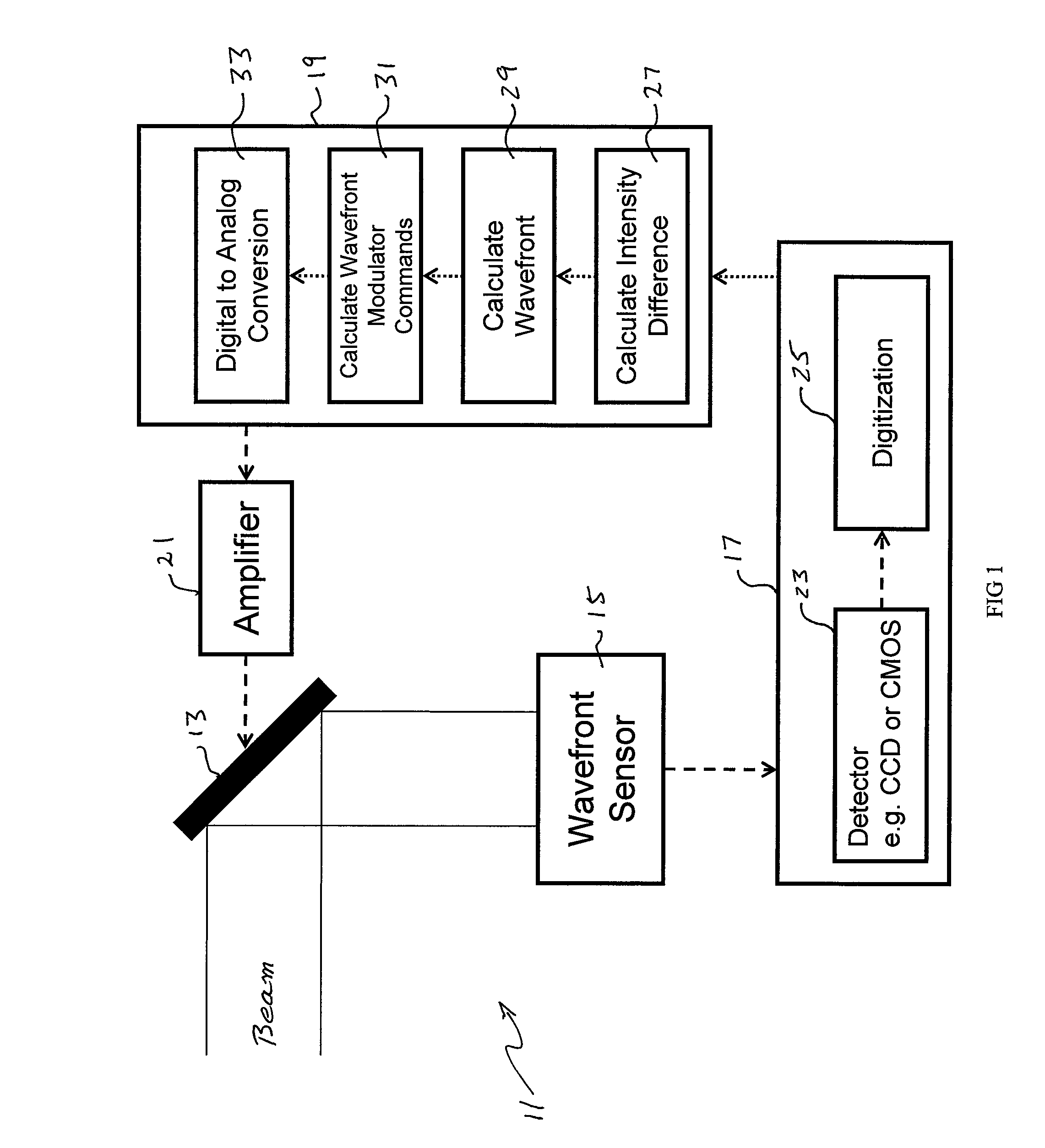
[0043]With reference to FIG. 3, adaptive optical system 71 includes a wavefront modulator 73 for reshaping the wavefront of beam 75. System 71 also includes wavefront sensor 77, data acquisition device 79, processor 81 and amplifier 83. Wavefront modulator 73 is, in the preferred embodiment, a deformable mirror (which includes actuators); sensor 77, a distorted grating wavefront sensor. As illustrated, data acquisition device 79 includes a detector 85 (e.g., a CCD or a CMOS) and a mechanism (e.g., a routine or hardware) 87 for digitizing the images captured by detector 85. Processor 81, in sharp contrast with the prior art, includes a routine 89 for processing the raw digital data from converter 87 and a digital to analog conversion routine 91. Variations of the foregoing include incorporating detector 85 into wavefront sensor 77. Further, converter 87 can be part of data acquisition device 79, incorporated into processor 81 or be a stand alone device. Amplifier 83 can be a separate...


PUM


Abstract

A system, for determining characteristics of a beam wavefront and reshaping such wavefront, including: apparatus for sampling the wavefront curvature and generating outputs; apparatus for reshaping the wavefront; and apparatus for receiving the outputs, proportioning the outputs to match the inputs need to drive controls for the reshaping apparatus, and sending the proportioned outputs to the reshaping apparatus. The reshaping apparatus is, preferably, a deformable mirror. The sampling apparatus includes a distorted grating. The method includes: positioning the sampling apparatus in the bean path; positioning a reshaping apparatus in the beam path; sampling the curvature of the wavefront and generating outputs representative of the curvature thereof; sending the generated outputs to the proportioning apparatus; proportioning the outputs to match the inputs needed to drive the controls of the reshaping apparatus; and sending the proportioned outputs to the reshaping apparatus to change the shape thereof.

Description

RELATED U.S. APPLICATION DATA[0001]This application is a continuation-in-part of and claims the priority of provisional application Ser. No. 60 / 958,480, filed Jul. 3, 2007.FIELD OF THE INVENTION[0002]This invention relates, in general, to wavefront characterization and correction. More particularly, the present invention relates to a method (and the associated apparatus) including the steps: of sampling the curvature of a wavefront with a curvature sampling device; generating outputs representative of the curvature of the wavefront; sending the generated outputs to a proportioning device; and proportioning the outputs from the curvature sampling device to match the inputs needed to drive the controls of a wavefront reshaping device. The invention also relates to apparatus and methods for determining at least some of the characteristics of the wavefront of a beam without the use of an artificially generated reference.BACKGROUND OF THE INVENTION[0003]U.S. Pat. No. 6,286,959 B1 (the “'...

Claims


Application Information

Patent Timeline
IPC IPC(8): G01J1/00
CPCG01J9/00
Inventor ERRY, GAVIN R. G.HARRISON, PAULHUNTER, BOYDBUTLER, EUGENE W.
Owner KESTREL CORP
Learn More