
Exhaust gas purification system for internal combustion engine and method for regenerating purification ability of exhaust gas purification device

a technology of exhaust gas purification system and purification device, which is applied in the direction of engines, mechanical equipment, machines/engines, etc., can solve the problems of reducing the purification ability of catalysts, limiting the effect of internal combustion engine operating performance, and reducing agents that cannot reach the exhaust gas purification device, etc., to achieve adequate suppression of sudden fluctuations in engine torque, inhibit deterioration in driveability, and high controllability

Inactive Publication Date: 2011-10-04
TOYOTA JIDOSHA KK
View PDF18 Cites 4 Cited by
  • Summary
  • Abstract
  • Description
  • Claims
  • Application Information

AI Technical Summary

Benefits of technology

This approach ensures more reliable and efficient regeneration of the purification ability by stabilizing reducing agent distribution and reducing the risk of agent escape or incomplete reaction, enhancing the overall regeneration process.

Problems solved by technology

Sulfur oxides (SOx) in the exhaust gas are also stored in the NOx catalyst, which results in SOx poisoning that reduces the purification ability of the catalyst.
It also limits the effect on the operating performance of the internal combustion engine.
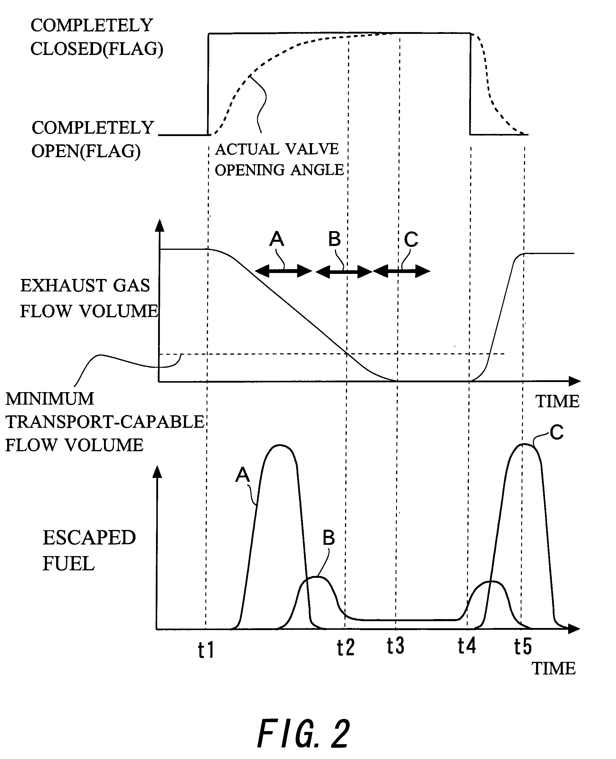
However, with the technology described above, when the flow volume of the exhaust gas in the exhaust gas purification device was reduced at a constant speed, for example, there was a risk that the reducing agent would not arrive at the exhaust gas purification device with the timing at which the reducing agent should be added.
There was also a risk that the reducing agent would pass through the exhaust gas purification device and escape.
As a result, it was sometimes difficult to supply the reducing agent to the entire exhaust gas purification device reliably and to regenerate the purification ability efficiently.

Method used


Image

  • Exhaust gas purification system for internal combustion engine and method for regenerating purification ability of exhaust gas purification device
  • Exhaust gas purification system for internal combustion engine and method for regenerating purification ability of exhaust gas purification device
  • Exhaust gas purification system for internal combustion engine and method for regenerating purification ability of exhaust gas purification device

Examples


Embodiment Construction

[0052]Best modes to carry out the present invention are explained in detail below as examples with reference to the drawings.

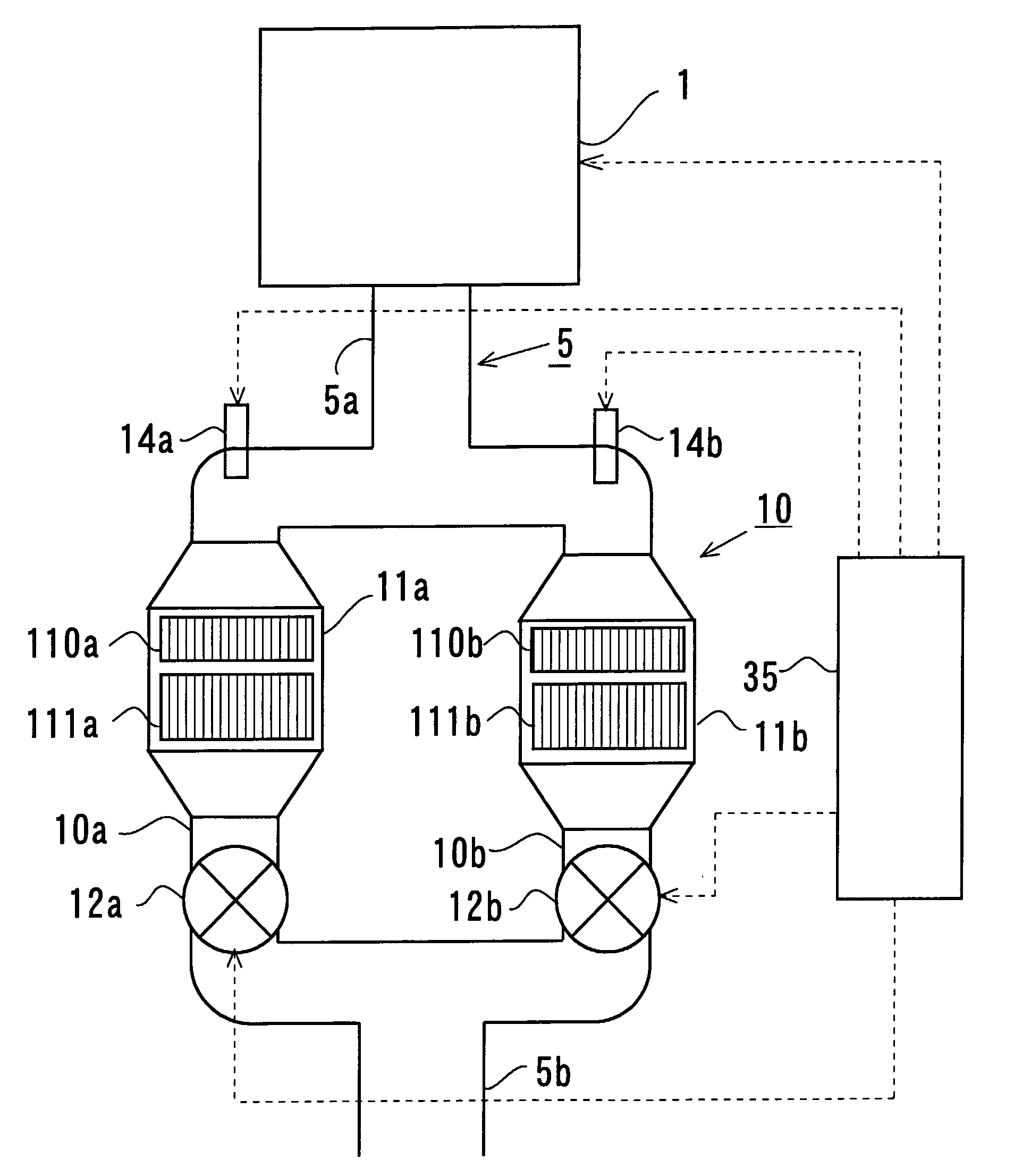
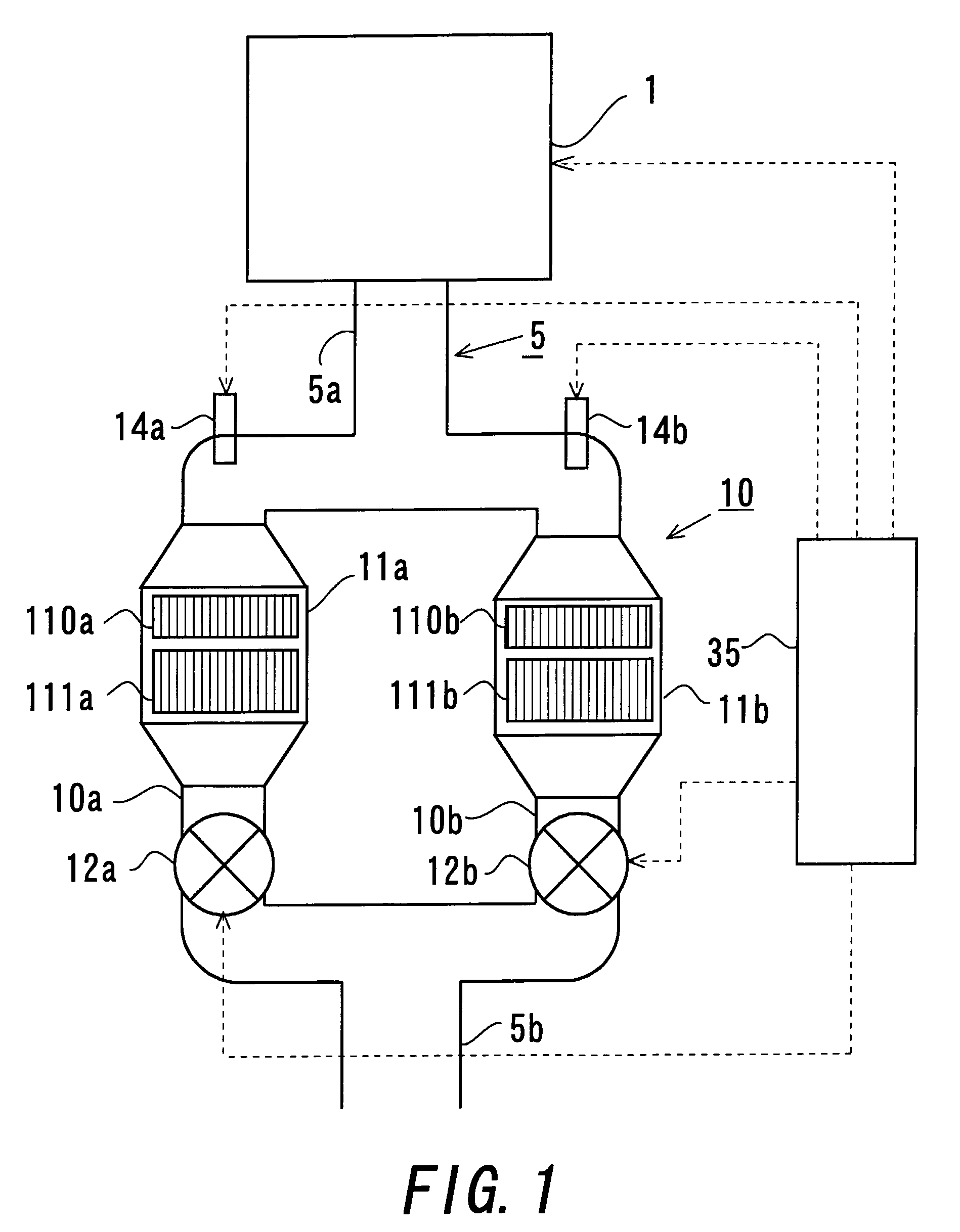
[0053]FIG. 1 is a drawing showing an overall configuration of an internal combustion engine, its exhaust system, and its control system in accordance with this embodiment. The internal combustion engine 1 shown in FIG. 1 is a diesel engine. In FIG. 1, the interior of the internal combustion engine 1 and its intake system are omitted.

[0054]In FIG. 1, an exhaust pipe 5, through which exhaust gas from the internal combustion engine 1 flows, is connected to the internal combustion engine 1. The exhaust pipe 5 is connected downstream to a muffler (not shown). An exhaust gas purification portion 10, which removes particulate matter (for example, soot), nitrogen oxides (NOx), and the like from the exhaust gas, is located within the exhaust pipe 5. Hereinafter, the portion of the exhaust pipe 5 that is upstream from the exhaust gas purification portion 10 is called a ...


PUM


Abstract

The problem is to regenerate the purification ability of an exhaust gas purification device more reliably or efficiently in an exhaust gas purification system that combines a plurality of branch passages branch off from an exhaust gas passage and exhaust gas purification devices. When the purification ability of an exhaust gas purification device is regenerated, in the branch passage where the exhaust gas purification device is provided whose purification ability is to be regenerated, the opening angle of an exhaust gas flow volume control valve is set to the minimum opening angle that can reliably transport a reducing agent that is added from a reducing agent addition section. While the opening angle is maintained, the reducing agent is added. After the addition of the reducing agent is complete, the opening angle of an exhaust gas flow volume control valve is closed completely.

Description

TECHNICAL FIELD[0001]The present invention relates to an exhaust gas purification system for an internal combustion engine and to a method for regenerating the purification ability of an exhaust gas purification device.BACKGROUND ART[0002]The exhaust gas of an internal combustion engine contains harmful substances such as nitrogen oxides (NOx) and the like. It is known that an exhaust system of an internal combustion engine is provided with a NOx catalyst to remove NOx from the exhaust gas in order to reduce emissions of these harmful substances. With this technology, for example, when a NOx storage-reduction catalyst is provided, the purification ability drops if the amount of stored NOx increases, so a reducing agent is supplied to the NOx storage-reduction catalyst, and the NOx stored in the catalyst is reduced and discharged. (Hereinafter, this process is called “NOx reduction processing”.) Sulfur oxides (SOx) in the exhaust gas are also stored in the NOx catalyst, which results...

Claims


Application Information

Patent Timeline
Patent Type & Authority Patents(United States)
IPC IPC(8): F01N3/00
CPCF01N3/0842F01N3/0871F01N9/00F01N13/0097F01N13/011F01N3/0821F01N3/0878F01N2260/14F01N2570/04F01N2610/03Y02T10/47F01N13/107Y02T10/40
Inventor NIIMI, KUNIAKITSUJIMOTO, KENICHIODA, TOMIHISAHIROTA, SHINYAUEDA, TAKANORI
Owner TOYOTA JIDOSHA KK
Learn More