Diagnostic system for automatic transmission

a diagnostic system and automatic transmission technology, applied in the direction of mechanical equipment, instruments, transportation and packaging, etc., can solve the problems of inability to release, deterioration of the shifting performance of the automatic transmission, and the diagnostic system still suffers a problem in terms of flexibility or freedom with which to perform fault diagnosis, so as to achieve a high degree of freedom and high reliability

Inactive Publication Date: 2011-10-04
TOYOTA JIDOSHA KK
View PDF13 Cites 8 Cited by
  • Summary
  • Abstract
  • Description
  • Claims
  • Application Information

AI Technical Summary

Benefits of technology

[0009]The invention was developed in view of the situations as described above, and one aspect of the invention is to provide a diagnostic system for an automatic transmission which is able to appropriately determine the presence of any fault of solenoid valves that control the hydraulic pressures applied to friction devices of the automatic transmission, with increased flexibility and freedom, irrespective of the frequency or tendency of operating each of the friction devices of the transmission.
[0011]Under the condition as mentioned above, all of the solenoid valves are basically freed from their functions (i.e., actuation of the corresponding friction devices) required of the automatic transmission. Therefore, even if the solenoids of the solenoid valves are forcedly energized for diagnostic purposes, the energization has absolutely no influence on the behavior of the vehicle. Thus, under the above-mentioned condition, fault diagnostics can be performed on any desired solenoid valve or valves, and the presence of faults of the solenoid valves can be appropriately determined with high degrees of flexibility and freedom. If all of the solenoid valves (solenoids) to be diagnosed are normal, the current monitored with respect to each of the solenoids behaves in accordance with the manner of energizing the solenoid. If any of the solenoids suffers a fault, such as a break or disconnection, for example, no current from the solenoid is detected even though the solenoid is energized. Also, if any of the solenoids suffers a fault, such as a short-circuit, a current from the solenoid is detected even though the solenoid is not energized. Thus, the diagnosis of each of the solenoids can be easily accomplished by monitoring the current passing through the solenoid for detection of any abnormality. In view of the fact that the above-described diagnostics can be performed without affecting the behavior of the vehicle at all, each of the solenoids may be energized using a certain test pattern, such as a pattern of regularly spaced pulses, which makes it easy to monitor current passing through the solenoid. In this case, further detailed diagnostics can be performed, which includes a diagnosis as to how the current monitored follows the test pattern according to which each solenoid is energized.
[0017]The condition that torque that can drive the driving wheels of the vehicle is not transmitted to the output shaft of the automatic transmission is advantageously satisfied based on the operation to stop the prime mover, namely, the operation to turn the ignition key off. Since a control system of the prime mover is able to cause a main relay connected to a vehicle-mounted battery to be switched off under control thereof, the main relay can be switched off only after various postprocessing, including the above-described diagnostics, is executed subsequently to turn-off of the ignition key. With the above arrangement, the solenoid valves are diagnosed each time the ignition key is operated to the “OFF” position, thus assuring an increased frequency with which each solenoid valve is diagnosed.
[0023]In general, the solenoid valve capable of regulating the hydraulic pressure of the hydraulic oil supplied to the friction device used for limp-home running of the vehicle, namely, the solenoid valve for use in limp-home running, is normally diagnosed with a relatively low frequency. However, if the solenoid valve for use in limp-home running goes out of order, the vehicle is not even able to run in the limp-home mode in the event of failure. Thus, the solenoid valve for use in limp-home running is especially required to be diagnosed at regular intervals. In the diagnostic system as described just above, the solenoid valve for use in limp-home running is included in the solenoid valves to be diagnosed according to the invention, and, therefore, the automatic transmission provided with the limp-home running function operates with a high degree of reliability even when the vehicle runs in the limp-home mode. Furthermore, since the above-described diagnostic system can easily select the solenoid valve(s) to be diagnosed, the solenoid valve for use in limp-home running, as well as the other solenoid valves, can be diagnosed with a high degree of freedom.

Problems solved by technology

In the automatic transmission as described above, if a fault, such as disconnection or a short-circuit, occurs to a solenoid of any of the solenoid valves, the transmission may suffer a problem that, for example, a friction device to be engaged for shifting is not able to be engaged, or a problem that a friction device to be released for shifting is not able to be released.
In this case, the automatic transmission may not be able to be shifted to the target gear position, or the automatic transmission may lock in itself, which naturally results in deterioration of the shifting performance of the automatic transmission.
Therefore, the frequency of diagnosing the solenoid valves inevitably varies from one solenoid valve to another, depending upon the manner of operating the automatic transmission itself, even though fault diagnoses may be performed on the solenoid valves in the above manner.
Thus, the diagnostic system still suffers a problem in terms of the flexibility or freedom with which fault diagnoses are performed.

Method used


Image

  • Diagnostic system for automatic transmission
  • Diagnostic system for automatic transmission
  • Diagnostic system for automatic transmission

Examples


Embodiment Construction

[0032]In the following description and the accompanying drawings, the present invention will be described in more detail with reference to exemplary embodiments.

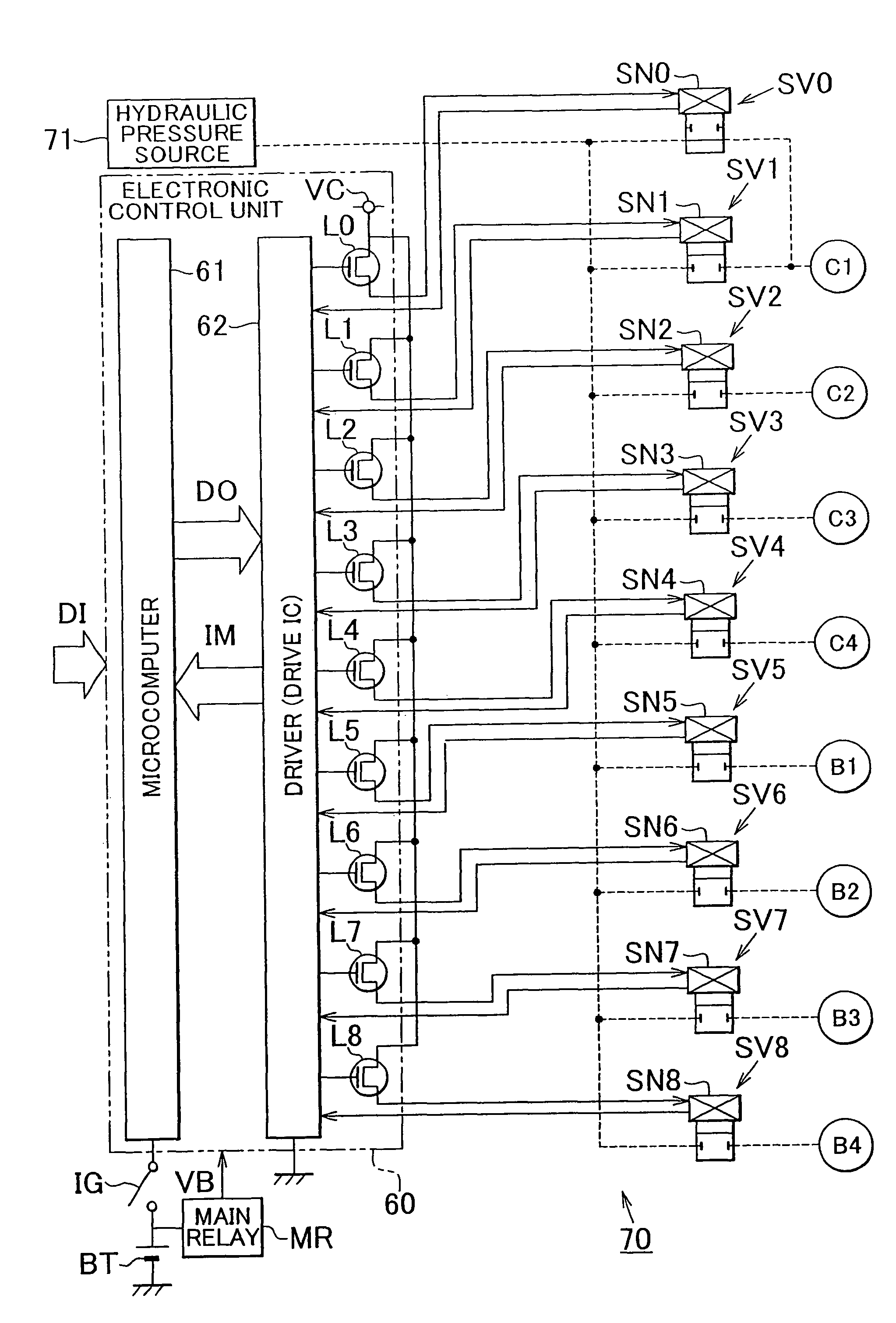
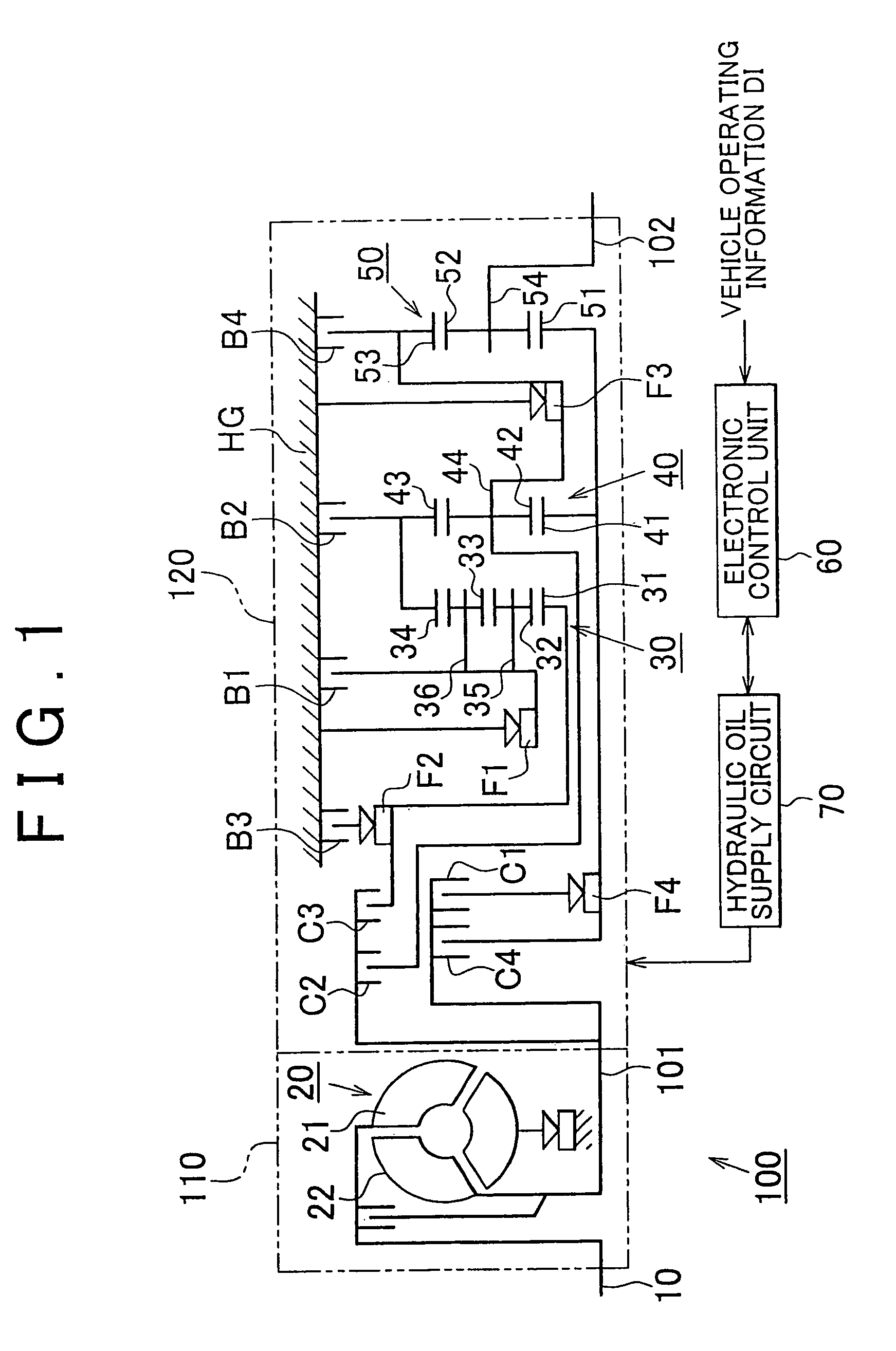
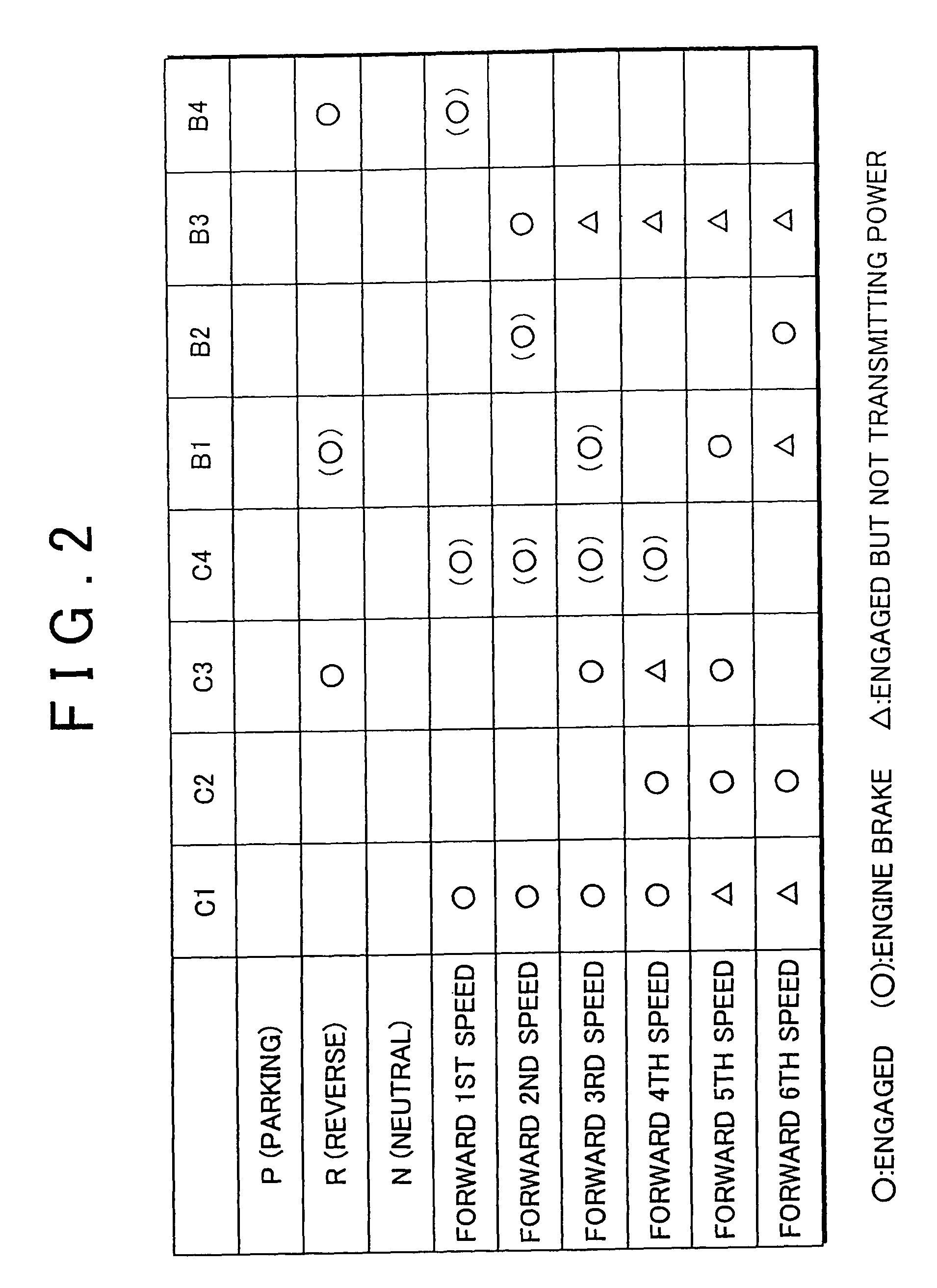
[0033]Referring to FIG. 1 through FIG. 4, a diagnostic system for an automatic transmission according to one embodiment of the invention will be described in detail. In this embodiment, the invention is applied to a diagnostic system for a forward six-speed automatic transmission installed on a vehicle. As shown in FIG. 1, the automatic transmission 100 consists principally of an input conversion unit 110 connected to a crankshaft 10 of an internal combustion engine as one example of prime mover installed on the vehicle, and a gear train unit 120 connected to driving wheels of the vehicle via a propeller shaft. The input conversion unit 110 includes a torque converter 20. As well known in the art, the torque converter 20 includes a pump impeller 21 coupled to the crankshaft 10, and a turbine runner 22 coupled to an input sha...


PUM


Abstract

A diagnostic system for an automatic transmission is provided in which a microcomputer determines that torque that can drive the driving wheels of the vehicle is not transmitted to an output shaft of the automatic transmission when the vehicle is stopped and the ignition key is operated to the OFF position, and performs forced energization of solenoids of solenoid valves associated with respective friction devices of the transmission, while monitoring current passing through the solenoid valves. If the current monitored does not match the current for energizing any of the solenoids, the microcomputer determines that the corresponding solenoid valve is at fault. Thus, the diagnostic system appropriately determines the presence of a fault of each solenoid valve for controlling the hydraulic pressure to each friction device, with increased flexibility and freedom.

Description

[0001]The disclosure of Japanese Patent Application No. 2006-212328 filed on Aug. 3, 2006, including the specification, drawings and abstract is incorporated herein by reference in its entirety.BACKGROUND OF THE INVENTION[0002]1. Field of the Invention[0003]The invention relates to a diagnostic system for an automatic transmission, which diagnoses an automatic transmission installed in a drive train of a vehicle to determine the presence of faults therein.[0004]2. Description of the Related Art[0005]As well known in the art, an automatic transmission installed in a drive train of the vehicle includes a plurality of friction devices, such as clutches and brakes, to which hydraulic pressure is selectively applied so as to engage the friction devices. With the selected friction device(s) thus engaged, a power transmission path, or a gear position of the transmission, is determined depending upon the operating conditions of the vehicle. More specifically, a hydraulic pressure source is ...

Claims


Application Information

Patent Timeline
Patent Type & Authority Patents(United States)
IPC IPC(8): G01M13/02F16H59/68F16H59/74F16H61/12F16H61/68F16H61/684F16H61/686F16H63/50
CPCF16H61/12F16H61/686F16H2061/1208F16H2200/0052F16H2200/201F16H2200/2051F16H2061/1268F16H59/68F16H61/00
Inventor NIWA, KENJISUGIMURA, TOSHIOMIZOBUCHI, MASAYASU
Owner TOYOTA JIDOSHA KK
Why Eureka
Try Eureka