Integrated capture of fossil fuel gas pollutants including CO2 with energy recovery

a fossil fuel gas and energy recovery technology, applied in the field of integrated capture of fossil fuel gas pollutants including co2 with energy recovery, can solve the problems of prohibitively expensive sub>2/sub>capture, a significant increase in effort and cost to bring under control, and achieve the effect of raising the cost of energy production

Active Publication Date: 2011-10-18
JUPITER OXYGEN CORP
View PDF24 Cites 70 Cited by
  • Summary
  • Abstract
  • Description
  • Claims
  • Application Information

AI Technical Summary

Benefits of technology

[0014]As will be explained in greater detail below, in association with an illustrative embodiment of the present invention, the process of the present invention, for capturing CO2 can also be applied to the removal of other pollutants. Further, the energy transfers involved in this process can be positioned for maximal recovery into the power generation cycle such that capturing CO2 need not unduly raise the cost of energy production.

Problems solved by technology

Unregulated and uncontrolled fossil fuel burning power plants have been responsible for a significant portion of this pollution.
Significantly, the carbon dioxide (CO2) stream, from combustion in such plants, has been found to be the more massive constituent of pollution, larger than any other pollutant stream, and so will now require a significant increase in effort and cost to bring under control.
Unfortunately, it has been found that including CO2 capture devices and processes to the present day series of separate processes used in pollution control and abatement, which are dedicated to the removal of single pollutant types, has proved to be prohibitively costly.

Method used


Image

  • Integrated capture of fossil fuel gas pollutants including CO2 with energy recovery
  • Integrated capture of fossil fuel gas pollutants including CO2 with energy recovery

Examples


Embodiment Construction

[0017]While the present invention is susceptible of embodiment in various forms, there is shown in the drawing a presently preferred embodiment that is discussed in greater detail hereafter. It should be understood that the present disclosure is to be considered as an exemplification of the present invention, and is not intended to limit the invention to the specific embodiments illustrated. It should be further understood that the title of this section of this application (“Detailed Description of the Illustrative Embodiment”) relates to a requirement of the United States Patent Office, and should not be found to limit the subject matter disclosed herein.

[0018]In this disclosure, the use of the disjunctive is intended to include the conjunctive. The use of the definite article or indefinite article is not intended to indicate cardinality. In particular, a reference to “the” object or “a” object is intended to denote also one of a possible plurality of such objects.

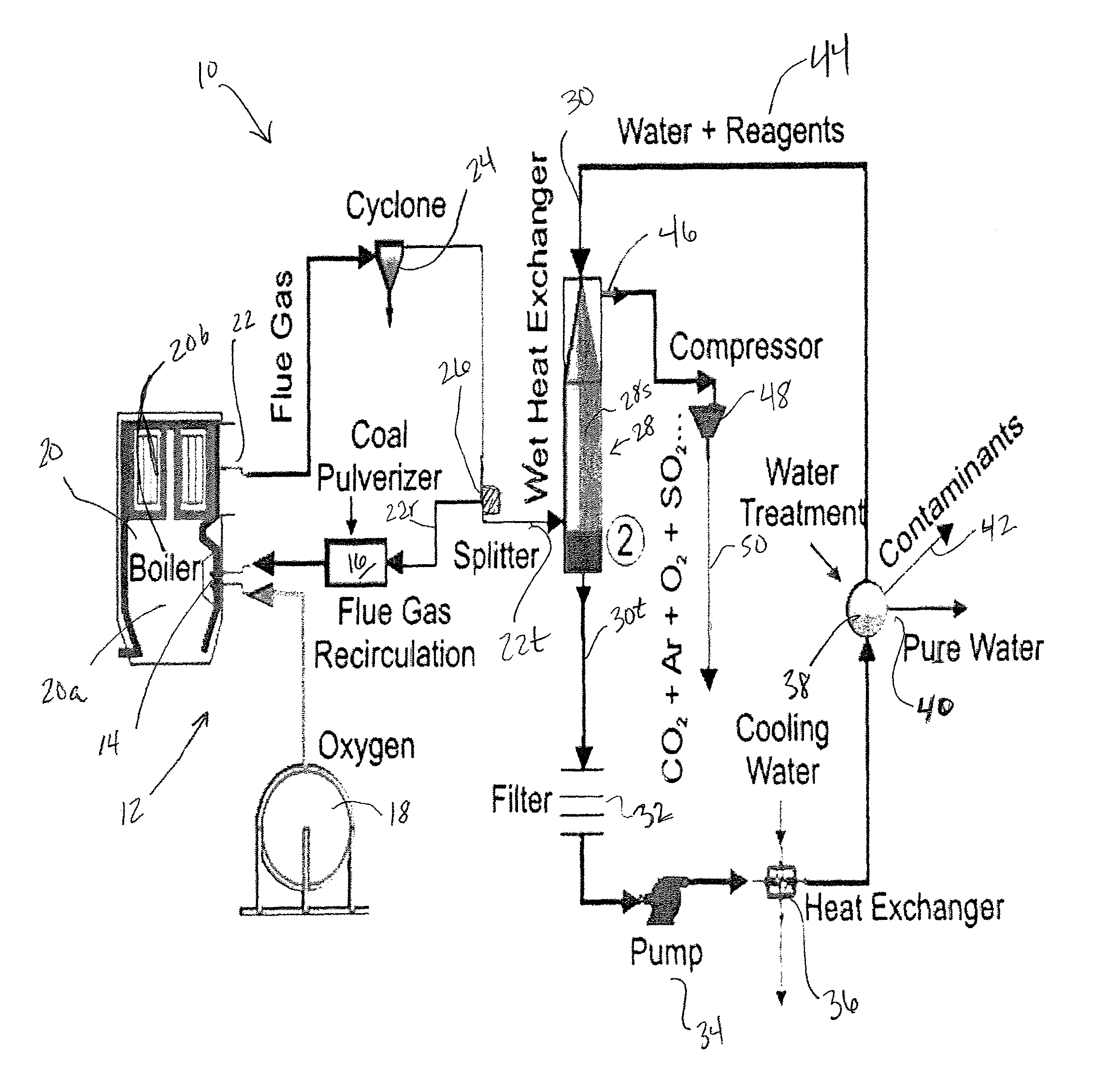
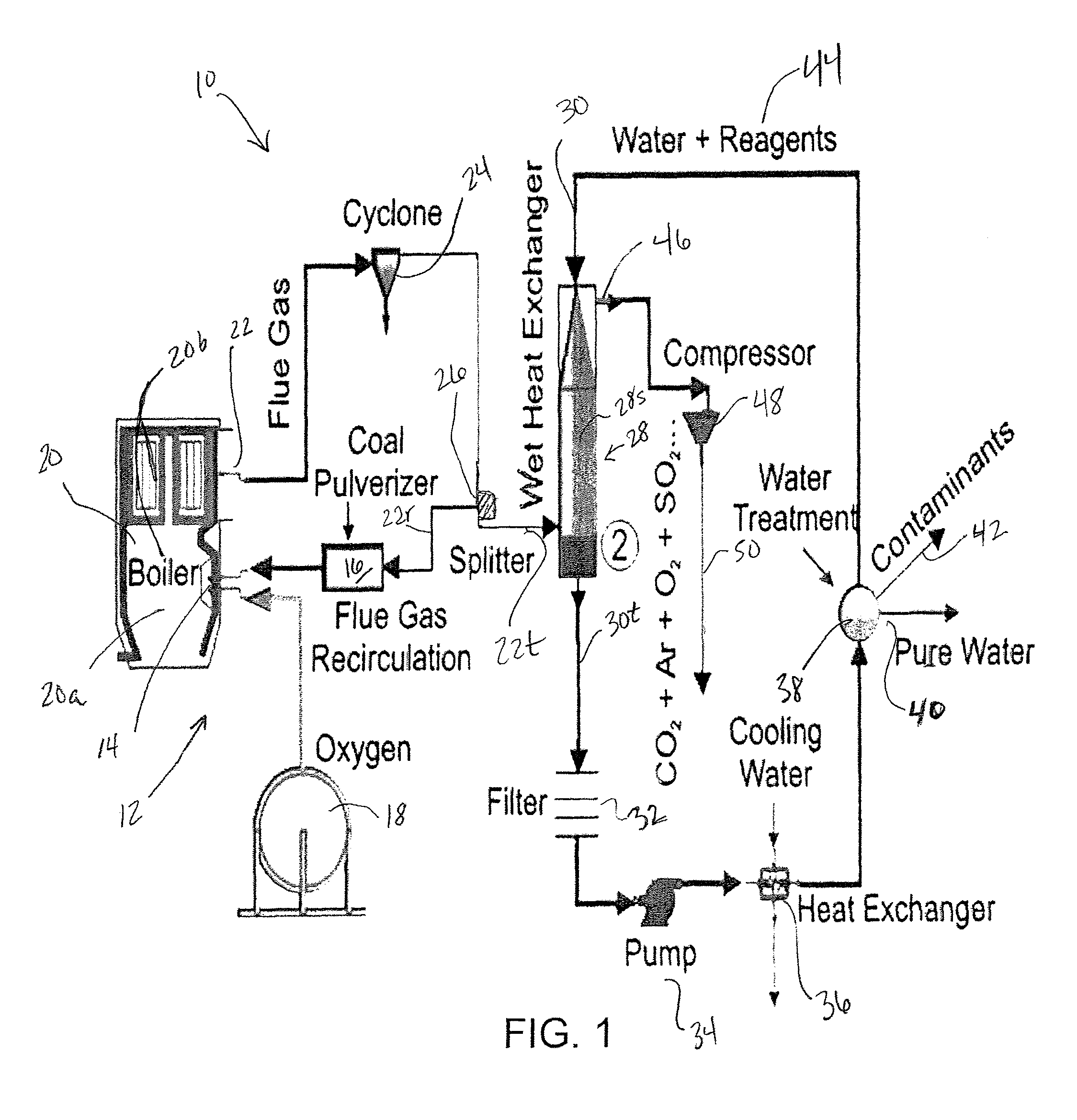
[0019]The present...


PUM

PropertyMeasurementUnit
temperatureaaaaaaaaaa
purityaaaaaaaaaa
heataaaaaaaaaa

Abstract

A method of reducing pollutants exhausted into the atmosphere from the combustion of fossil fuels. The disclosed process removes nitrogen from air for combustion, separates the solid combustion products from the gases and vapors and can capture the entire vapor / gas stream for sequestration leaving near-zero emissions. The invention produces up to three captured material streams. The first stream is contaminant-laden water containing SOx, residual NOx particulates and particulate-bound Hg and other trace contaminants. The second stream can be a low-volume flue gas stream containing N2 and O2 if CO2 purification is needed. The final product stream is a mixture comprising predominantly CO2 with smaller amounts of H2O, Ar, N2, O2, SOX, NOX, Hg, and other trace gases.

Description

CROSS REFERENCE TO RELATED APPLICATION[0001]This application is a continuation-in-part of commonly owned and co-pending U.S. patent application Ser. No. 11 / 306,437, filed on Dec. 28, 2005, hereby incorporated by reference. This application also claims priority to U.S. Provisional Patent Appl. No. 60 / 808,095, filed on May 24, 2006, also incorporated by reference.[0002]The United States Government has rights in this invention pursuant to employer / employee agreements between the U.S. Department of Energy (DOE) and some of the inventors and through license agreements with the assignee of the invention.BACKGROUND OF THE INVENTION[0003]The climatic changes resulting from the rise of greenhouse gas concentration in the atmosphere are becoming an increasingly important concern to those who regulate the operation and flue gas output of fossil-fuel combustion-based power plants. Unregulated and uncontrolled fossil fuel burning power plants have been responsible for a significant portion of th...

Claims


Application Information

Patent Timeline
Patent Type & Authority Patents(United States)
IPC IPC(8): B01D53/14
CPCF23C9/00F23D1/00F23J15/04F23J15/06F23L7/007F23J2215/50F23J2219/40Y02E20/363F23J2219/80F23L2900/07001Y02E20/322Y02E20/344F23J2219/70Y02E20/30Y02E20/32Y02E20/34
Inventor OCHS, THOMAS L.SUMMERS, CATHY A.GERDEMANN, STEVEORYSHCHYN, DANYLO B.TURNER, PAULPATRICK, BRIAN R.
Owner JUPITER OXYGEN CORP
Why Eureka
Try Eureka