Reformer

a technology of reformer and reformer chamber, which is applied in the direction of lighting and heating apparatus, separation processes, physical/chemical process catalysts, etc., to achieve the effect of improving thermal efficiency, effective use, and extending the heat transfer area of the reforming chamber for combustion gas

Inactive Publication Date: 2011-10-18
IDEMITSU KOSAN CO LTD
View PDF16 Cites 6 Cited by
  • Summary
  • Abstract
  • Description
  • Claims
  • Application Information

AI Technical Summary

Benefits of technology

[0011]However, the fuel reforming apparatus described in Patent document 1 can improve thermal efficiency by a vacuum thermally insulating chamber, but, for example, in the case of a small fuel cell system whose generated electric power is about 1 KW, further reduction in an amount of radiation heat per unit area is required to bring the thermal efficiency in a reformer to the same level.

Problems solved by technology

Therefore, for the fuel cell system, the most important challenge is how to efficiently produce hydrogen gas from the hydrocarbon material, and various techniques have been disclosed for fuel reforming apparatuses and reformers which produce hydrogen gas.

Method used


Image

  • Reformer
  • Reformer
  • Reformer

Examples


first embodiment

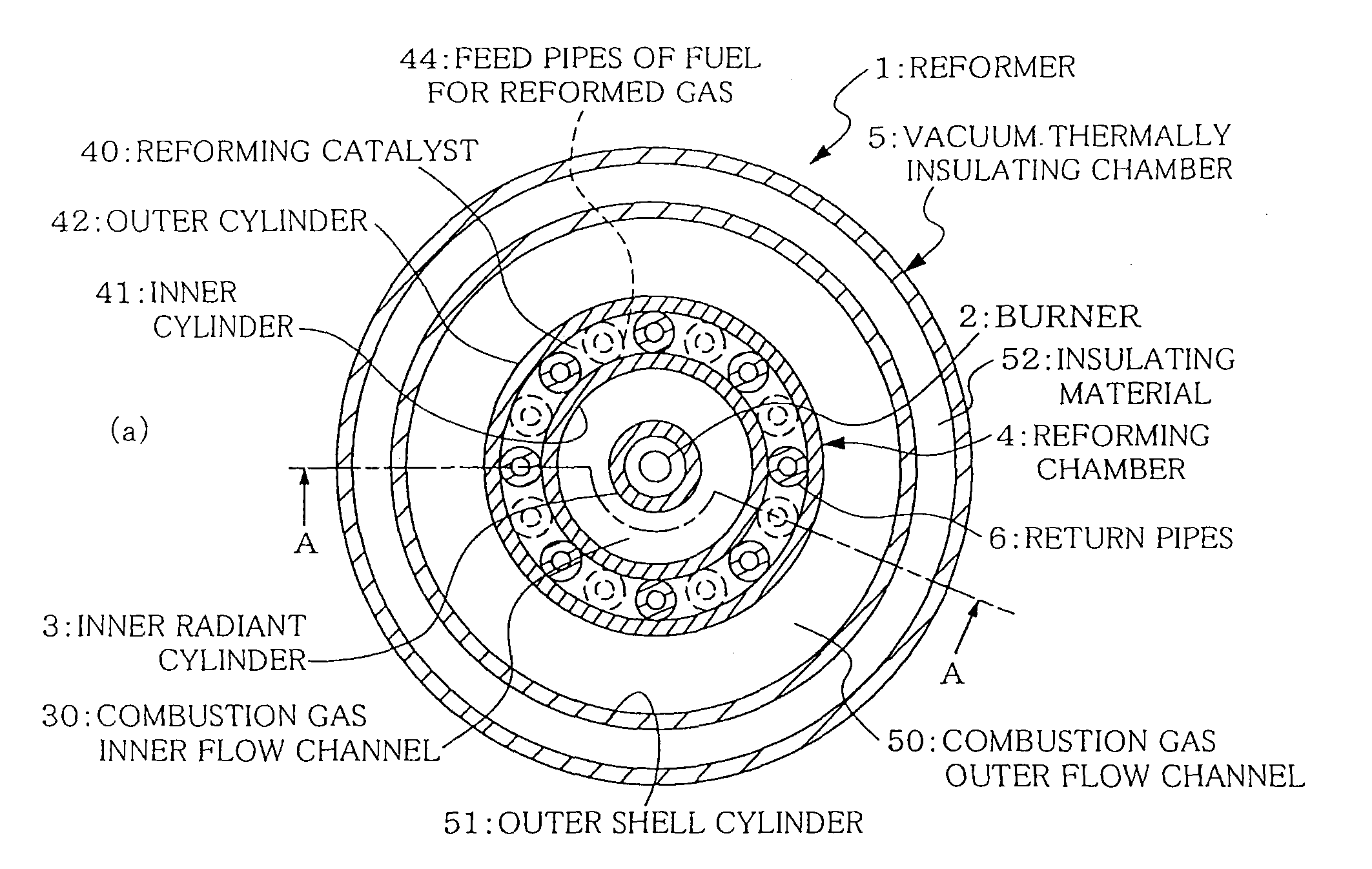
[0040]FIG. 1 is a schematic view of a reformer according to a first embodiment of the present invention, wherein (a) shows a sectional view in an upper surface direction and (b) shows a sectional view of A-A.

[0041]In FIG. 1, in the configuration of a reformer 1, there are provided, from the center to the outer periphery thereof, a burner 2, an inner radiant cylinder 3, a reforming chamber 4 and a vacuum thermally insulating chamber 5.

[0042]The reformer 1 in the present embodiment is installed in a fuel reforming apparatus of a fuel cell system. Although not shown in the drawings, there are provided, under the reformer 1, associated equipments necessary for the fuel reforming apparatus, for example a water evaporator, a hydrocarbon material vaporizer, and a mixing nozzle which mixes water vapor with a hydrocarbon material, and so on.

[0043]It is to be noted that the reformer 1 of the present invention is not limited to a case of being unitized as the fuel reforming apparatus, and, for...

second embodiment

[0067]FIG. 4 is a schematic view of an external fin of a reformer according to a second embodiment of the present invention, wherein (a) shows an enlarged sectional view and (b) shows a sectional view in which the external fin is attached.

[0068]In FIG. 4, a reformer la has a configuration in which a fin 7 is provided in combustion gas outer flow channel 50.

[0069]The fin 7 comprises a fin barrel 72 to be inserted into an outer shell cylinder 51, and a fin body 71 helically provided in a protruding manner in the inner side of the fin barrel 72. Combustion gas contacts the fin 7 and the flowing direction thereof is changed, such that the heat transfer efficiency to a reforming chamber 4 can be enhanced.

[0070]In this fin 7, a through-hole is bored in the fin body 71, and a mounting screw 73 comprising a complete thread is inserted into this through-hole and fixed at an optional height position.

[0071]It is to be noted that configuration of other parts is substantially similar to that in ...


PUM

PropertyMeasurementUnit
temperatureaaaaaaaaaa

Abstract

A reformer that produces reformed gas from a hydrocarbon material includes a reforming chamber having an inner cylinder and an outer cylinder; a reforming catalyst filled in the reforming chamber; a burner that heats the reforming catalyst and fuel of reformed gas; a combustion gas outer flow channel through which combustion gas of the burner flows along an outer side surface of the reforming chamber; a combustion gas inner flow channel through which the combustion gas of the burner flows along an inner side surface of the reforming chamber; and a plurality of return pipes as a reformed gas flow channel.

Description

TECHNICAL FIELD[0001]The present invention relates to a reformer to be used in a fuel reforming apparatus of a fuel cell system, and particularly, it relates to a reformer which improves in thermal efficiency by reason of heating both inner and outer side surfaces of a double cylindrical reforming chamber by combustion gas produced when a burner is turned on, and in the reforming chamber, providing “return pipes” through which a produced reformed gas flows.BACKGROUND ART[0002]In a fuel cell system, reverse to the electrolysis of water, oxygen is electro-chemically reacted with hydrogen gas produced from hydrocarbon material in order to generate electricity and heat (warm water) during the chemical reaction.[0003]The above fuel cell system uses oil-based fuel such as naphtha, kerosene and so on, or gas-based fuel such as city gas, etc. as the hydrocarbon material, and this hydrocarbon material is mixed with steam to produce gaseous fuel for reformed gas, and then this fuel for reform...

Claims


Application Information

Patent Timeline
Patent Type & Authority Patents(United States)
IPC IPC(8): B01J19/00B01J8/00C01B3/38H01M8/06
CPCB01J8/0257B01J8/0285B01J8/067C01B3/384H01M8/0631B01J2208/00221B01J2208/00504Y02E60/50C01B2203/0233C01B2203/066C01B2203/0811B01J2208/0053C01B3/26C01B3/38
Inventor HIGASHINO, KAZUYUKI
Owner IDEMITSU KOSAN CO LTD
Why Eureka
Try Eureka