Fuel cell and fuel cell stack

a fuel cell and stack technology, applied in the field of fuel cells, can solve the problems of excessive temperature difference between the oxygen-containing gas supplied to the fuel cell stack prior to the power generation reaction and the exhaust gas, affecting the efficiency reducing the durability of the fuel cell, so as to prevent an excessive increase in the temperature of the exhaust gas, improve heat efficiency, and reduce the temperature difference

Inactive Publication Date: 2011-10-18
HONDA MOTOR CO LTD
View PDF22 Cites 2 Cited by
  • Summary
  • Abstract
  • Description
  • Claims
  • Application Information

AI Technical Summary

Benefits of technology

[0010]In order to address and solve the above problems, an object of the present invention is to provide a fuel cell and a fuel cell stack having a simple structure, in which it is possible to reliably prevent an excessive increase in the temperature of the exhaust gas, to prevent a non-uniform temperature distribution in the fuel cell stack, and to effectively prevent damage to the electrolyte electrode assembly and the separator, thereby improving power generation performance.

Problems solved by technology

Under these circumstances, durability of the fuel cell is lowered, and operation of the fuel cell stack cannot be performed stably.
Further, since the temperature of the exhaust gas after combustion becomes higher than the operating temperature, the temperature difference between the oxygen-containing gas supplied to the fuel cell stack prior to the power generation reaction and the exhaust gas becomes excessively large.
Therefore, a significant non-uniform temperature distribution occurs within the fuel cell stack, and power generation performance is degraded undesirably.
Therefore, a significant non-uniform temperature distribution occurs in the separator 4a, and power generation performance is degraded undesirably.

Method used


Image

  • Fuel cell and fuel cell stack
  • Fuel cell and fuel cell stack
  • Fuel cell and fuel cell stack

Examples


first embodiment

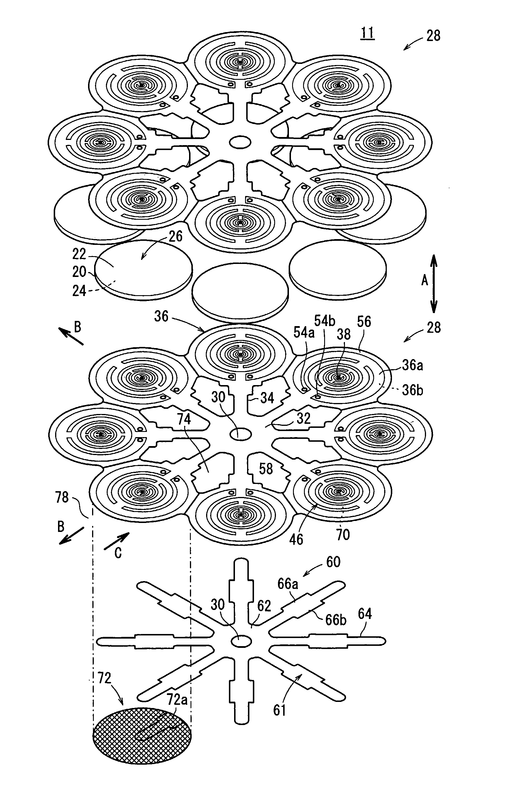
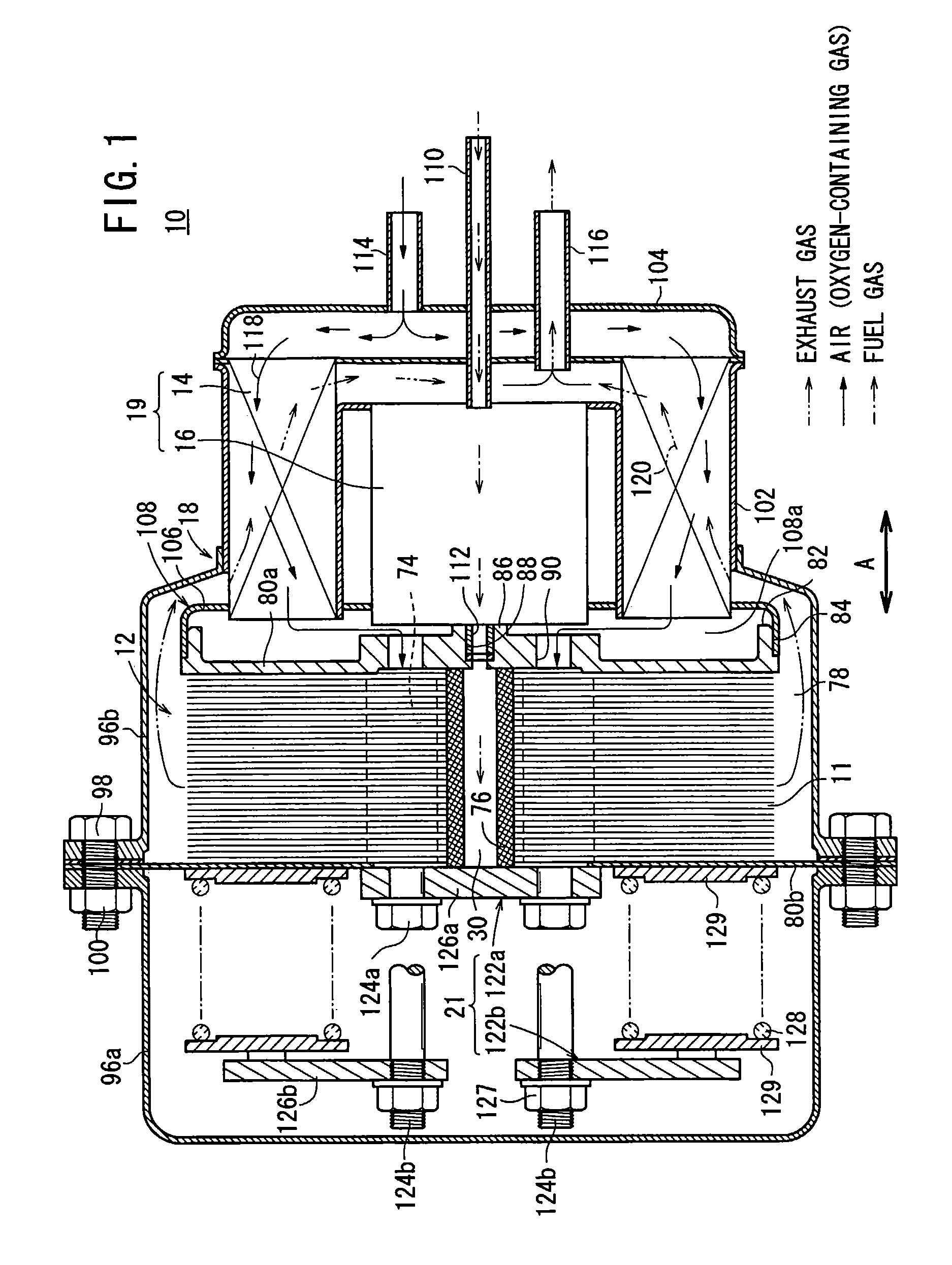
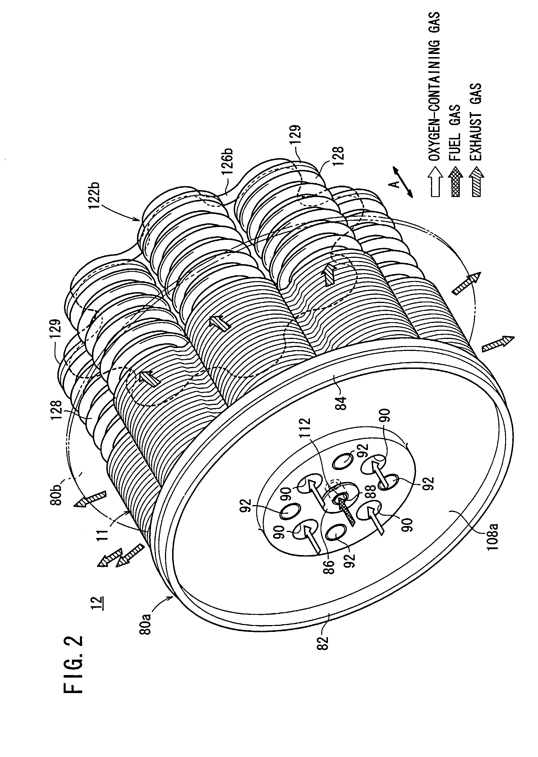
[0058]FIG. 1 is a partial cross sectional view showing a fuel cell system 10 including fuel cells 11 according to the present invention. FIG. 2 is a perspective view schematically showing a fuel cell stack 12 formed by stacking a plurality of the fuel cells 11 in a direction indicated by the arrow A.

[0059]The fuel cell system 10 is used in various applications, including stationary and mobile applications. For example, the fuel cell system 10 may be mounted on a vehicle. As shown in FIG. 1, the fuel cell system 10 includes the fuel cell stack 12, a heat exchanger 14, a reformer 16, and a casing 18. The heat exchanger 14 heats an oxygen-containing gas before it is supplied to the fuel cell stack 12. The reformer 16 reforms fuel in order to produce a fuel gas. The fuel cell stack 12, the heat exchanger 14, and the reformer 16 are disposed within the casing 18.

[0060]In the casing 18, a fluid unit 19, including at least the heat exchanger 14 and the reformer 16, is disposed on one side ...

second embodiment

[0119]In the second embodiment, the load in the stacking direction is efficiently transmitted through the protrusions 146 of the circular disk 36. Therefore, the fuel cells 140 can be stacked together with a small load, thereby reducing distortions in the electrolyte electrode assemblies 26 and the separators 142.

[0120]The protrusions 146 on the surface 36b of the circular disk 36 are formed by etching or the like as solid portions. Thus, the shape, positions, and density of the protrusions 146 can be changed arbitrarily and easily, depending on the flow state and / or fluidic conditions of the oxygen-containing gas, whereby a desired flow of the fuel gas can be achieved. Further, since the protrusions 146 are formed as solid portions, the protrusions 146 cannot be deformed, and thus, the load is reliably transmitted through the protrusions 146, and electricity is efficiently collected through the protrusions 146.

third embodiment

[0121]FIG. 12 is an exploded perspective view showing a fuel cell 160 according to the present invention.

[0122]The fuel cell 160 has a separator 162, wherein a fuel gas discharge channel 164 is formed on a surface of the separator 162 facing the anode 24. As shown in FIGS. 12 and 13, the fuel gas discharge channel 164 is formed on the surface 36a of each circular disk 36. The fuel gas discharge channel 164 includes discharge grooves 166a, 166b connected to the fuel gas channel 46, and a lid member 168, which is provided on the surface 36a, for thereby closing the discharge grooves 166a, 166b.

[0123]The discharge grooves 166a, 166b are provided in place of the discharge holes 54a, 54b (which are not required in the third embodiment), at positions corresponding to the discharge holes 54a, 54b along the plate shaped extensions 57a, 57b, and being opened toward the oxygen-containing gas supply unit 74. Each of the discharge grooves 166a, 166b includes a step (not shown), wherein the lid...


PUM

PropertyMeasurementUnit
operating temperatureaaaaaaaaaa
circumferenceaaaaaaaaaa
deformable elasticaaaaaaaaaa

Abstract

A fuel cell includes a separator having a circular disk. On one surface of the circular disk, a fuel gas channel is provided for supplying a fuel gas to an anode, and on the other surface of the circular disk, an oxygen-containing gas channel is provided for supplying air to a cathode. The fuel gas channel has an end point at an outer circumferential end of the anode. A fuel gas discharge channel is connected to an end point of the fuel gas channel, such that the consumed fuel gas is emitted to an oxygen-containing gas supply unit, from a position spaced outwardly from the outer circumference of an electrolyte electrode assembly.

Description

[0001]This application is a 35 U.S.C. 371 national stage filing of International Application No. PCT / JP2006 / 325121, filed 11 Dec. 2006, which claims priority to Japanese Patent Application No. 2005-378494 filed on 28 Dec. 2005 in Japan. The contents of the aforementioned applications are hereby incorporated by reference.TECHNICAL FIELD[0002]The present invention relates to a fuel cell formed by stacking an electrolyte electrode assembly and a separator. The electrolyte electrode assembly includes an anode, a cathode, and an electrolyte interposed between the anode and the cathode. Further, the present invention relates to a fuel cell stack formed by stacking a plurality of fuel cells.BACKGROUND ART[0003]Typically, a solid oxide fuel cell (SOFC) having a seal free (sealless) structure employs an electrolyte made up of an ion-conductive solid oxide such as stabilized zirconia. The electrolyte is interposed between an anode and a cathode to form an electrolyte electrode assembly. The e...

Claims


Application Information

Patent Timeline
Patent Type & Authority Patents(United States)
IPC IPC(8): H01M8/04
CPCH01M8/0247H01M8/04014H01M8/04089H01M8/2425H01M8/0258H01M8/0612Y02E60/50H01M8/2432H01M8/2457H01M8/2483H01M8/2484H01M8/02H01M8/24
Inventor DAN, KOJI
Owner HONDA MOTOR CO LTD
Why Eureka
Try Eureka