Coupler device

a technology of coupling device and transmission line, which is applied in the direction of multiple-port network, electrical apparatus, waveguide, etc., can solve the problems of reducing the insertion loss affecting the insertion efficiency of the coupling device, so as to improve the thermal resistance, reduce the thickness, and improve the thermal resistance.

Active Publication Date: 2011-10-25
TTM TECH INC
View PDF10 Cites 22 Cited by
  • Summary
  • Abstract
  • Description
  • Claims
  • Application Information

AI Technical Summary

Benefits of technology

[0019]The present invention addresses the needs described above by providing an unwound / rewound spiral that offers the benefits of a miniaturized low insertion loss coupler having matched (symmetric) coupler port impedances. The coupler of the present invention also provides a coupler having a reduced thickness and strategically placed signal traces such that the device of the present invention offers improved thermal resistance characteristics. Of course, the improved thermal resistance translates into improved power handling capabilities. The unwound / rewound spiral coupler line configuration of the present invention provides an increased line density suitable for implementing miniaturized low loss coupler devices. Furthermore, the transmission lines are disposed in a manner as to protect them from potential hazardous environment to increase the maximum operational temperature.

Problems solved by technology

However, the coupler usually has an “insertion loss” which accounts for the differences between the input signal and the output signals.
At the isolation port, there is destructive interference of RF waves and the RF signals cancel such that there is no appreciable signal available at the fourth port.
In practice, the cancellation is not perfect and a residual signal may be detected.
Edge-side and / or broadside coupler topologies have drawbacks in that they are relatively large in the x-y direction because of the line length required.
Meandered broadside coupled lines also have size and density limitations.
This reality, of course, limits the spatial density of meandered line configurations.
This affects the coupler's ability to divide and combine RF signals, particularly in high efficiency amplifiers, where the amplifier impedance changes with the amplitude of the signal.
As alluded to above, the so-called spiral coupler structure has a serious drawback, however, since port locations are disposed on the inside and outside of the spiral.
This asymmetry seriously impacts the coupling performance of the device.
However, an issue that may impact the performance of spiral couplers relates to the thermal resistance of the coupled structure.
Accordingly, the RF signal power level must be lowered or the device will be impaired or destroyed by the heat generated by the RF signal itself.
Equally important, if not more, is the insertion loss of the device.

Method used


Image

  • Coupler device
  • Coupler device
  • Coupler device

Examples


Embodiment Construction

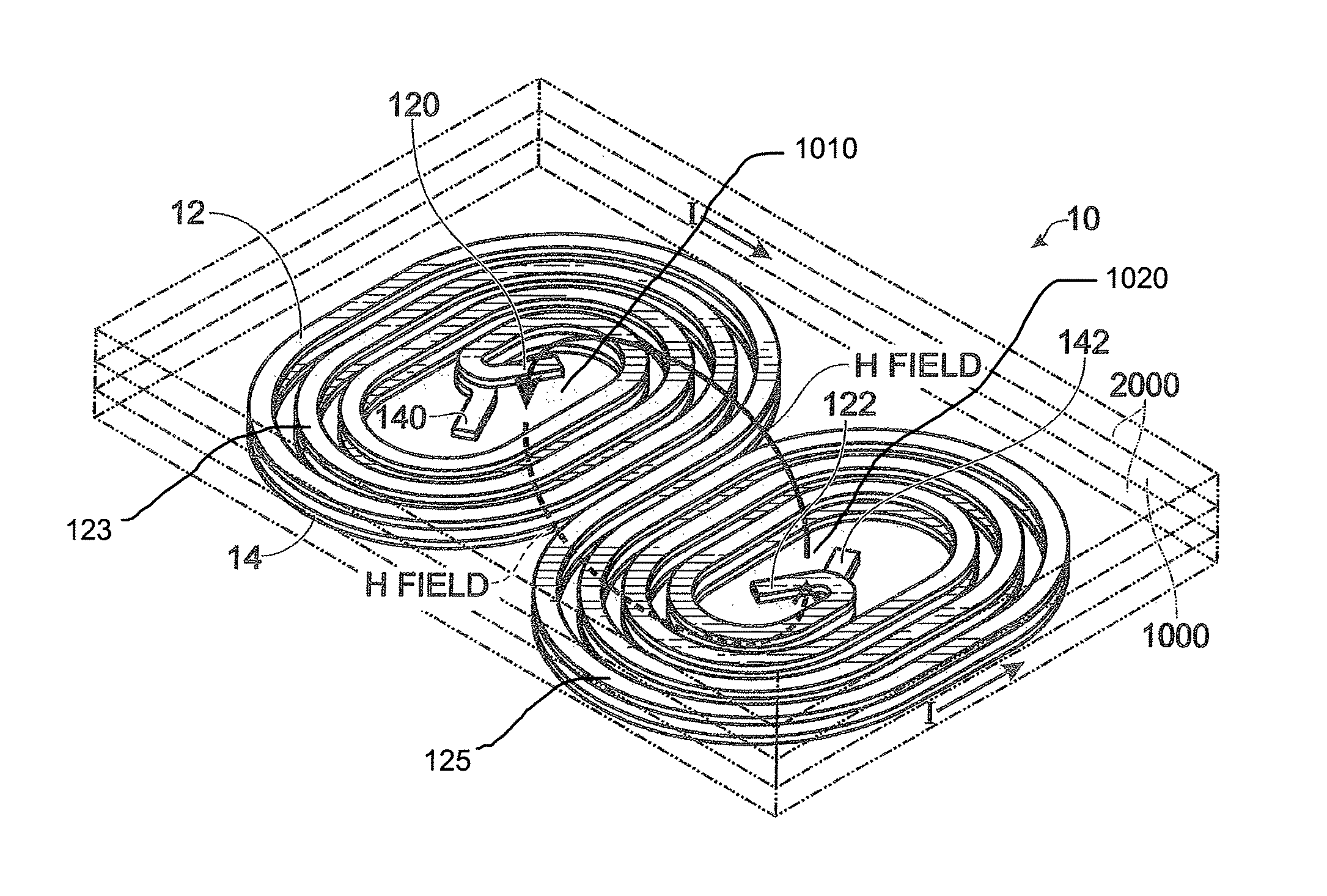
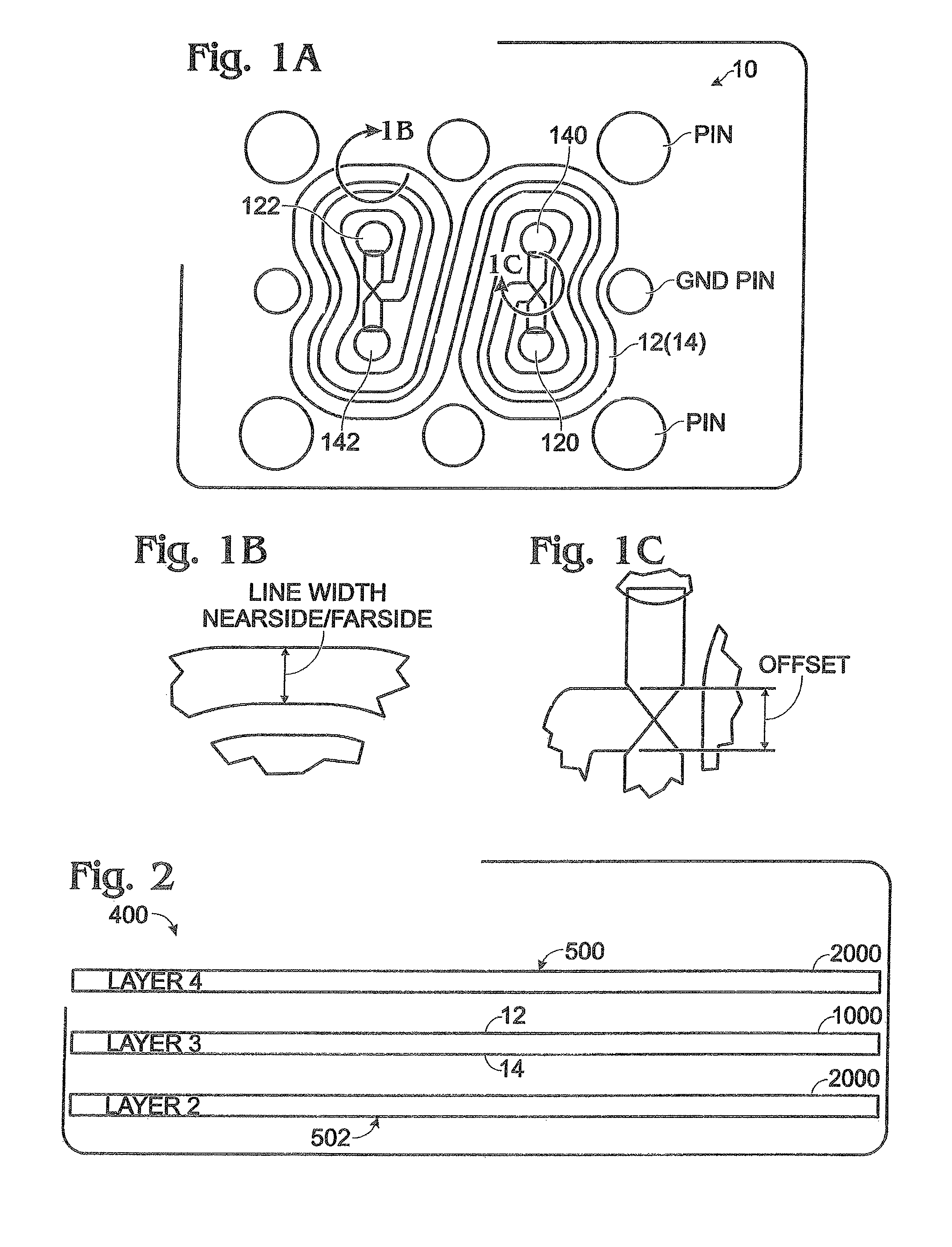
[0036]Reference will now be made in detail to the present exemplary embodiments of the invention, examples of which are illustrated in the accompanying drawings. Wherever possible, the same reference numbers will be used throughout the drawings to refer to the same or like parts. An exemplary embodiment of the coupler of the present invention is shown in FIG. 1, and is designated generally throughout by reference numeral 10.

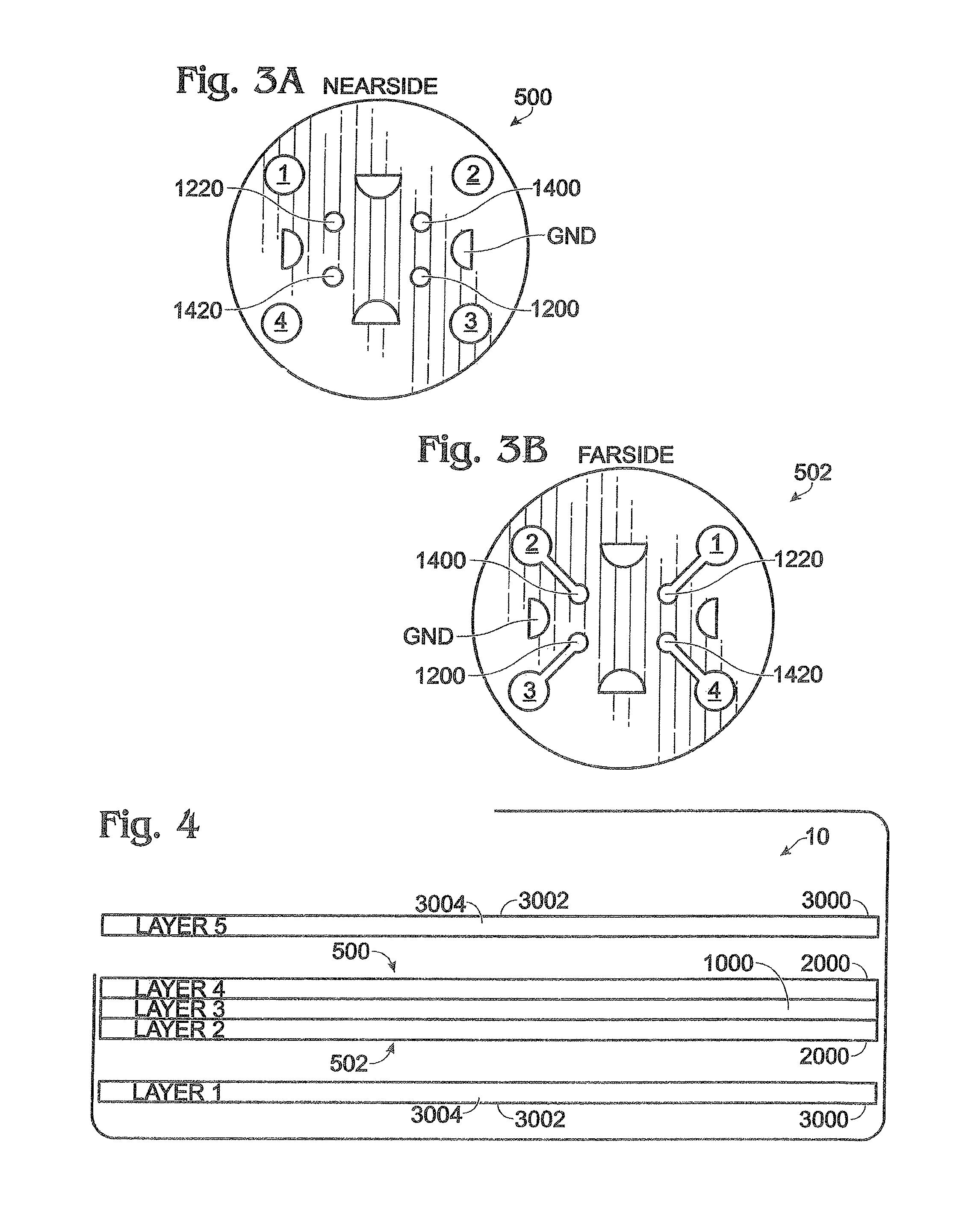
[0037]As embodied herein and depicted in FIGS. 1A-1C, plan and detail views of an unwound / rewound coupler 10 in accordance with an embodiment of the present invention are disclosed. Transmission line 12 is disposed on one side of a dielectric layer 1000 and another transmission line layer 14 is disposed on the other side of the dielectric layer 1000 (layer 3) to form the unwound / rewound coupler structure of the present invention. The term “unwound / rewound” refers to the plan-view arrangement (depicted in FIG. 1A) that provides two substantially spiral shaped “win...


PUM


Abstract

The present invention is directed to a coupler that includes a coupler structure including at least one first transmission line disposed on a first major surface of a coupler dielectric substrate and at least one second transmission line disposed on a second major surface of the coupler dielectric substrate. The coupler structure includes four symmetric ports such that each port of the four symmetric ports is characterized by substantially identical impedance characteristics. A first ground plane structure is coupled to the coupler structure and including a first outer dielectric material and a first conductive exterior layer disposed substantially parallel to the first major surface. A second ground plane structure is coupled to the coupler structure and including a second outer dielectric material and a second conductive exterior layer disposed substantially parallel to the second major surface. A thermal path is disposed between the coupler structure and at least one of the first conductive exterior layer or second conductive exterior layer. The thermal path is characterized by a thermal resistance substantially within a range between 15 W/mK and 50 W/mK, such that the coupler has a power handling capability of more than 800 W per square inch of heat sink interface.

Description

CROSS-REFERENCE TO RELATED APPLICATIONS[0001]This application claims priority to U.S. Provisional Patent Application Ser. No. 61 / 031,511, filed on Feb. 26, 2008, the content of which is relied upon and incorporated herein by reference in its entirety, and the benefit of priority under 35 U.S.C. §119(e) is hereby claimed.BACKGROUND OF THE INVENTION[0002]1. Field of the Invention[0003]The present invention relates generally to radio-frequency (RF) and / or microwave components, and particularly to RF and / or microwave coupled transmission line components.[0004]2. Technical Background[0005]A coupler is a four-port passive device that is used to combine, split and / or direct an RF signal within an RF circuit in a predictable manner. A coupler may be implemented by disposing two transmission lines in relatively close proximity to each other. The main transmission line includes a first (input) port and a second (output) port. The secondary transmission line includes a third (output) port and ...

Claims


Application Information

Patent Timeline
Patent Type & Authority Patents(United States)
IPC IPC(8): H01P5/18H01P3/08
CPCH01P5/185
Inventor WITAS, TOMASZ M.LUGERT, MICHAEL J.KIRKEBY, NIELS H.
Owner TTM TECH INC
Why Eureka
Try Eureka