Method and apparatus for injecting atomized fluids

a technology of atomized fluid and injector, which is applied in the direction of fuel injecting pumps, machines/engines, separation processes, etc., can solve the problems of affecting the performance of the engine, affecting the efficiency of the engine, and the use of such aqueous urea solutions, etc., to achieve enhanced performance atomizer and reduce the effect of engine exhaus

Active Publication Date: 2011-11-01
TENNECO AUTOMOTIVE OPERATING CO INC
View PDF33 Cites 43 Cited by
  • Summary
  • Abstract
  • Description
  • Claims
  • Application Information

AI Technical Summary

Benefits of technology

[0011]The present invention provides improved methods and apparatus for injecting a reagent, such as an aqueous urea solution, into an exhaust stream in order to reduce emissions from engine exhaust. In particular, the injector of the present invention is an enhanced performance atomizer for use with any engine, such as a diesel, natural gas, jet, turbine, fuel cell, or other engine type.
[0014]In addition, the present invention provides further improvements over the injector of the '603 patent, including increased magnetic pull strength of the metering plug over a wide temperature range, prolonged life of the injector valve and associated actuating components, and cooling with the urea throughout the injector. Additionally, the present invention incorporates adjustable spray quality characteristics on line, and interchangeability of orifice plates for multiple size applications. The ribbed injector body provides additional cooling capability.
[0015]The present invention may be further adapted to provide an injector for injecting hydrocarbons particularly for the purpose of particulate reduction in a diesel exhaust. The combination of pulse width modulation providing instantaneous timing control and mechanical atomization techniques is appropriate for providing small quantities of hydrocarbons with precise timing. The cooling aspects provided by the present invention allow the injector to survive the hot exhaust conditions as well as prevent pre-ignition of the hydrocarbon.
[0018]The injector may further comprise a reagent inlet extending into the injector and a reagent outlet extending out of the injector. The reagent inlet and reagent outlet may communicate with the whirl chamber via a hollow portion of the metering plug. The reagent inlet, the reagent outlet, and the hollow portion of the metering plug may provide a flow path for reagent through the injector, thereby enabling cooling of the injector. The flow path for the reagent through the injector may be provided independently of the position of the metering plug.
[0019]A metering orifice located in the injector body may control the flowrate of cooling reagent flowing through the injector at a given inlet pressure.

Problems solved by technology

Such engines are said to run “lean” or on a “lean mixture.” However, this increase in fuel economy is offset by undesired pollution emissions, specifically in the form of oxides of nitrogen (NOx).
However, use of such an aqueous urea solution involves many disadvantages.
Urea is highly corrosive and attacks mechanical components of the SCR system, such as the injectors used to inject the urea mixture into the exhaust gas stream.
Solidified urea may foul moving parts of the injector and clog any openings, rendering the injector unusable.
In addition, if the urea mixture is not finely atomized, urea deposits will form in the catalytic reactor, inhibiting the action of the catalyst and thereby reducing the SCR system effectiveness.
However, high injection pressures often result in over-penetration of the injector spray plume into the exhaust stream, causing the plume to impinge on the inner surface of the exhaust pipe opposite the injector.
Over-penetration leads to inefficient use of the urea mixture and reduces the range over which the vehicle can operate with reduced NOx emissions.
Further, aqueous urea is a poor lubricant.
This characteristic adversely affects moving parts within the injector and requires that special fits, clearances and tolerances be employed between relatively moving parts within an injector.
This characteristic adversely affects mating surfaces requiring enhanced sealing resources in many locations.

Method used


Image

  • Method and apparatus for injecting atomized fluids
  • Method and apparatus for injecting atomized fluids
  • Method and apparatus for injecting atomized fluids

Examples


Embodiment Construction

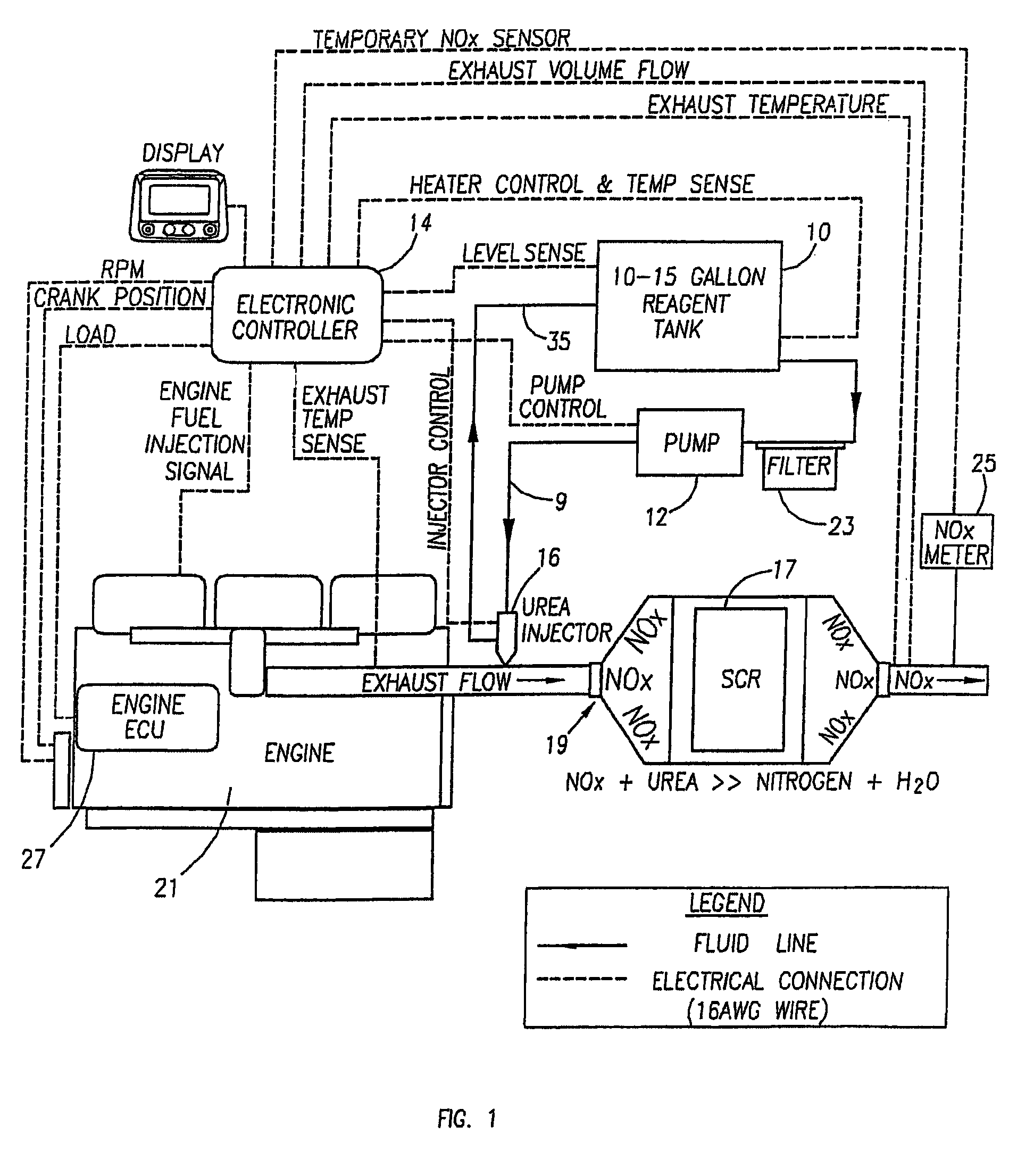
[0032]The ensuing detailed description provides exemplary embodiments only, and is not intended to limit the scope, applicability, or configuration of the invention. Rather, the ensuing detailed description of the exemplary embodiments will provide those skilled in the art with an enabling description for implementing an example embodiment of the invention. It should be understood that various changes may be made in the function and arrangement of elements without departing from the spirit and scope of the invention as set forth in the appended claims. It should also be understood that although the present teachings may be described in connection with diesel engines and the reduction of NOx emissions, the present teachings can be used in connection with any one of a number of exhaust streams, such as, by way of non-limiting example, those from diesel, gasoline, turbine, fuel cell, jet or any other power source outputting a discharge stream. Moreover, the present teachings can be use...


PUM


Abstract

Methods and apparatus for injecting reagent, such as an aqueous urea solution, into an exhaust stream in order to reduce emissions from an engine exhaust. The present teachings can use a whirl plate having a plurality of whirl slots surrounding an exit orifice of an injector, which produce a high velocity rotating flow in the whirl chamber. When the rotating flow of reagent is passed through the exit orifice into an exhaust stream, atomization occurs from a combination of centrifugal force and shearing of the reagent by air as it jets into the exhaust stream.

Description

CROSS-REFERENCE TO RELATED APPLICATIONS[0001]This application is a continuation-in-part of U.S. patent application Ser. No. 11 / 112,039 filed on Apr. 22, 2005, which claims the benefit of U.S. Provisional Application No. 60 / 565,356, filed Apr. 26, 2004. This application is also a continuation-in-part of U.S. patent application Ser. No. 11 / 714,718, filed Mar. 5, 2007, which claims the benefit of U.S. Provisional Application No. 60 / 565,356, filed Apr. 26, 2004. The entire disclosures of the above applications are incorporated herein by reference.BACKGROUND OF THE INVENTION[0002]The present invention relates generally to the reduction of emissions produced by lean burn engines. In particular, the present invention provides methods and apparatus for injecting reagent, such as an aqueous urea solution, into an exhaust stream in order to reduce oxides of nitrogen (NOx) emissions from diesel engine exhaust. Alternately, the present invention can be adapted for injecting a hydrocarbon reagen...

Claims


Application Information

Patent Timeline
Patent Type & Authority Patents(United States)
IPC IPC(8): F02D1/06
CPCF01N3/2066F01N2610/00F01N2610/02F01N2610/03F01N2610/11F01N2610/1453F02M53/04F02M53/08F02M61/162Y02T10/24Y02T10/12B01D53/94B05B1/02F01N3/28F01N3/36
Inventor MARTIN, SCOTT M.THOMAS, STEPHEN M.CHAMBERS, ALISON A.TARABULSKI, THEODORE J.SANTANGELI, P. ROBERTBRODERICK, R. GIFFORD
Owner TENNECO AUTOMOTIVE OPERATING CO INC
Why Eureka
Try Eureka