Electrolysis apparatus

a technology of electrolysis apparatus and electrodes, applied in the field of electrolysis, can solve the problems of reducing the effectiveness and practicability of such approaches, low efficiency of operation of these electrolysers, and low efficiency, and achieve the effect of reducing capability

Active Publication Date: 2011-11-01
LG FUEL CELL SYST
View PDF11 Cites 7 Cited by
  • Summary
  • Abstract
  • Description
  • Claims
  • Application Information

AI Technical Summary

Problems solved by technology

Although commercial water electrolysis is available at low temperatures through use of known technology the efficiency of operation for these electrolysers is relatively low.
Use of high temperature fuel cell technology is inhibited by the necessity for such high temperature fuel cells to operate at temperatures in excess of 800° C. and typically in a range 800° C.-1000° C. In such circumstances it is necessary to use specific heaters which diminish effectiveness and practicability of such approaches.
Unfortunately there is a significant disadvantage with current hydrogen production via water electrolysis in that, as indicated above, there is a relatively low efficiency.
Such low efficiency necessitates the use of a relatively high electricity consumption rate rendering the costs of the hydrogen produced by water electrolysis as too expensive for commercial viability relative to that currently produced through steam re-forming.
It will also be understood that the equipment cost for current water electrolysers is high again significantly contributing to making water electrolysis the more expensive option for hydrogen production when compared to steam re-forming of natural gas or other hydro carbons.

Method used


Image

  • Electrolysis apparatus
  • Electrolysis apparatus
  • Electrolysis apparatus

Examples


first embodiment

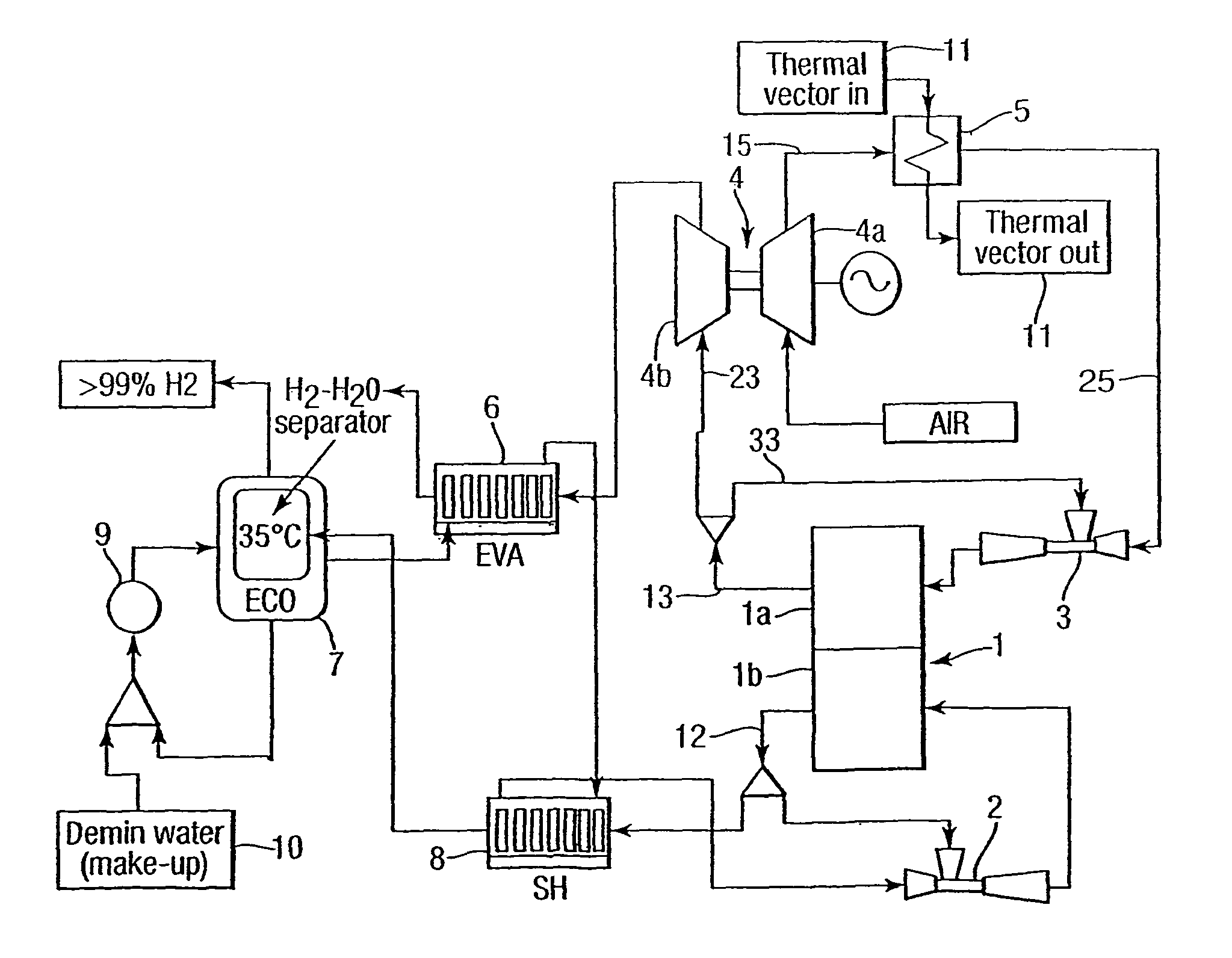
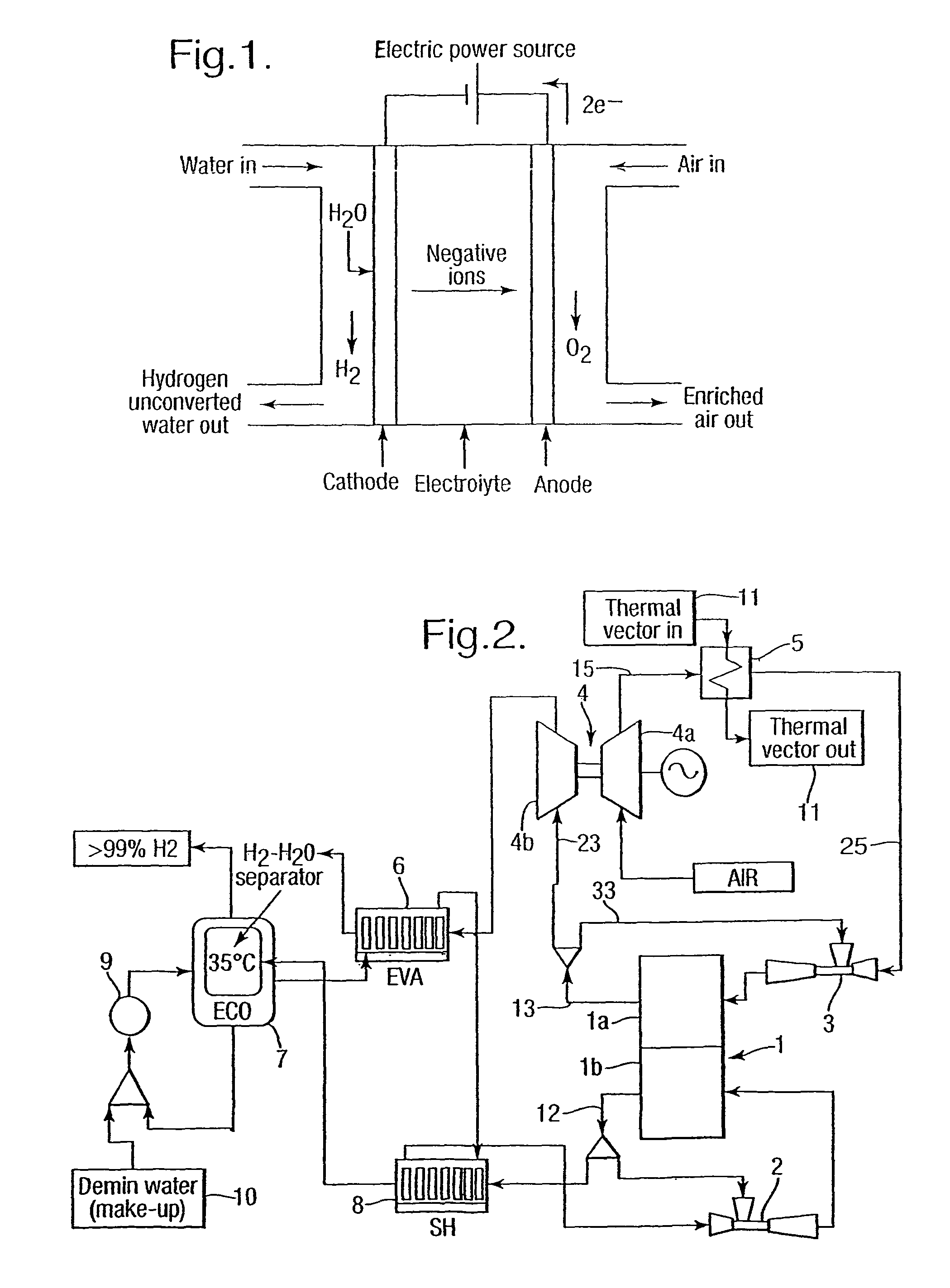
[0026]FIG. 2 provides a schematic illustration of a water electrolysis apparatus in accordance with certain aspects of the present invention. This embodiment and other embodiments are given as examples and the approach described may be utilised in respect of electrolysis apparatus to produce products other than hydrogen. Thus, a stack 1 comprises an anode portion and a cathode portion to which compressed air is provided from the ejector 3 and steam from an ejector 2 are respectively presented. Operation of the water electrolysis apparatus will be described below, but it will be appreciated that by reversal the present invention utilises a typical solid oxide fuel cell construction with minimal modifications.

[0027]The stack 1 as indicated compromises a solid oxide electrolyte with an anode side and a cathode side. In such circumstances compressed air from the ejector 3 is directed towards the anode 1a in the water electrolysis embodiment in accordance with one aspect of the present i...

second embodiment

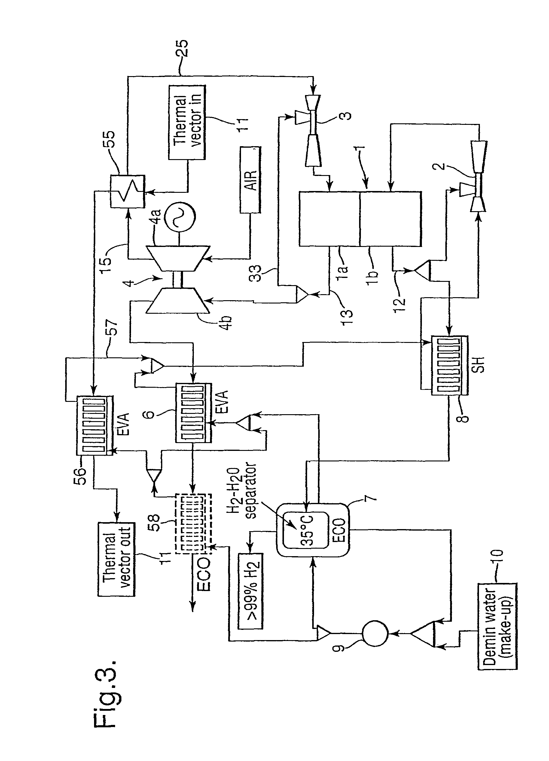
[0044]The amount of compressed air flow per stack 1 is limited by the maximum, producible steam flow rate from the internal heat recuperation process within the water electrolysis cycle, that is to say recovery at the gas turbine outlet. An alternative or second embodiment of a water electrolysis apparatus is depicted in FIG. 3 in which additional steam generation capacity is provided by exploiting heat taken from a heat exchanger 55 utilised in order to provide heat for steam generation. It will be understood that the temperature at the outlet from the heat exchanger 55 will generally be in the range of at least 350-400° C. to allow sufficient approach to delta T to the input temperature of the air coming from the compressor.

[0045]In FIG. 3 like for like components are similarly numbered to those referenced in FIG. 2 and additional description provided by additional features of this second embodiment. In such circumstances by use of the output heat from the heat exchanger 55 it wil...


PUM

PropertyMeasurementUnit
temperatureaaaaaaaaaa
temperaturesaaaaaaaaaa
temperatureaaaaaaaaaa

Abstract

Solid oxide stacks used as fuel cells generate electricity from hydrogen or other sources. By an electrolysis process such standard fuel cells can be operated in order to create hydrogen or other electro chemical by-products. Unfortunately stacks generally operate at relatively high temperatures which will be difficult to sustain purely on economic grounds. In such circumstances less efficient operation can be achieved at lower temperatures where the air-specific resistance is higher by balancing with the electrical power input in order to cause the disassociation required. In such circumstances by provision of an incident heat source, whether that be through a heat exchanger heating the compressed air flow, or recycling of a proportion of exhaust from the stack, or combustion of a product from stack disassociation the result will be a sustaining electrolysis operation reducing the amount of expensive electrical supply required to achieve dissociation.

Description

CROSS-REFERENCE TO RELATED APPLICATIONS[0001]This application is a continuation of International Application No. PCT / GB2006 / 003614, filed Sep. 29, 2006, designating the United States. This application also claims foreign priority under 35 U.S.C. 119 and 365 to United Kingdom patent application No. 0521984.5, filed Oct. 28, 2005.BACKGROUND OF THE INVENTION[0002]The present invention relates to electrolysis and for example utilisation of fuel cell technologies in order to generate hydrogen as a fuel for other uses.[0003]Electrolysis apparatus is known for a number of applications and it is proposed to use water electrolysis as a simple and clean technology for hydrogen production. Electrolysis is the reverse process to fuel oxidation in fuel cells. A schematic of the process is illustrated in FIG. 1. In an electrolysis process steam is dis-associated on a cathode with formation of hydrogen molecules. In solid oxide cells the cathode reaction is as follows:H2O+2e−=H2+O2−[0004]Oxygen io...

Claims


Application Information

Patent Timeline
Patent Type & Authority Patents(United States)
IPC IPC(8): C25B9/08C25B1/04C25B9/19C25B9/17C25B15/08H01M8/12H01M8/18
CPCC25B1/04C25B9/06C25B15/08H01M8/186Y02E60/525H01M2008/1293Y02E60/366Y02E60/528Y02P20/129Y02E60/36Y02E60/50C25B9/17H01M8/18H01M8/04
Inventor BALESTRINO, CRISTIANOAGNEW, GERARD D.BOZZOLO, MICHELE
Owner LG FUEL CELL SYST
Why Eureka
Try Eureka