
Cylinder head for an internal combustion engine

a technology for internal combustion engines and cylinder heads, which is applied in the direction of machines/engines, cylinders, gas passages, etc., can solve the problems of insufficient cooling of the cylinder head described in ep 1 722 090 a2, higher thermal load of the cylinder head with integrated exhaust manifolds, and penalty for fuel economy, etc., to achieve the effect of sufficient material strength

Active Publication Date: 2011-11-22
FORD GLOBAL TECH LLC
View PDF14 Cites 26 Cited by
  • Summary
  • Abstract
  • Description
  • Claims
  • Application Information

AI Technical Summary

Benefits of technology

The patent text describes a cylinder head for an internal combustion engine that has integrated exhaust manifolds and ducts to improve engine performance. By shortening the exhaust gas ducts and reducing the length of the cooling jacket, the engine has lower thermal load and higher efficiency. The cylinder head has a compact design with a reduced weight and improved packaging. The technical effects of the patent text include reduced turbocharger lag, increased exhaust gas temperature, and improved fuel economy and emissions control.

Problems solved by technology

The cooling of the cylinder head described in EP 1 722 090 A2 proved to be inadequate in practice due to thermal loading in the region where the exhaust gas ducts converge into the overall exhaust duct.
To prevent melting, the fuel / air mixture is enriched whenever high exhaust gas temperatures are expected, which results in more fuel being injected than can by burned by the air quantity provided, thus a penalty in fuel economy.
A cylinder head with integrated exhaust manifolds is subject to higher thermal load than a conventional cylinder head equipped with an outside manifold particularly in the areas where ducts converge.
Thus, such a configuration has increased cooling requirements.
Because the exhaust gas ducts are shortened, according to an embodiment of the disclosure, a potential issue is that dynamic wave processes in the cylinders can interact with each other and impede flow.
Thus, the potential disadvantage of the dynamic pressure waves of grouped cylinder impacting gas flow through cylinders is largely overcome by the selection of cylinder groups.

Method used


Image

  • Cylinder head for an internal combustion engine
  • Cylinder head for an internal combustion engine
  • Cylinder head for an internal combustion engine

Examples


Embodiment Construction

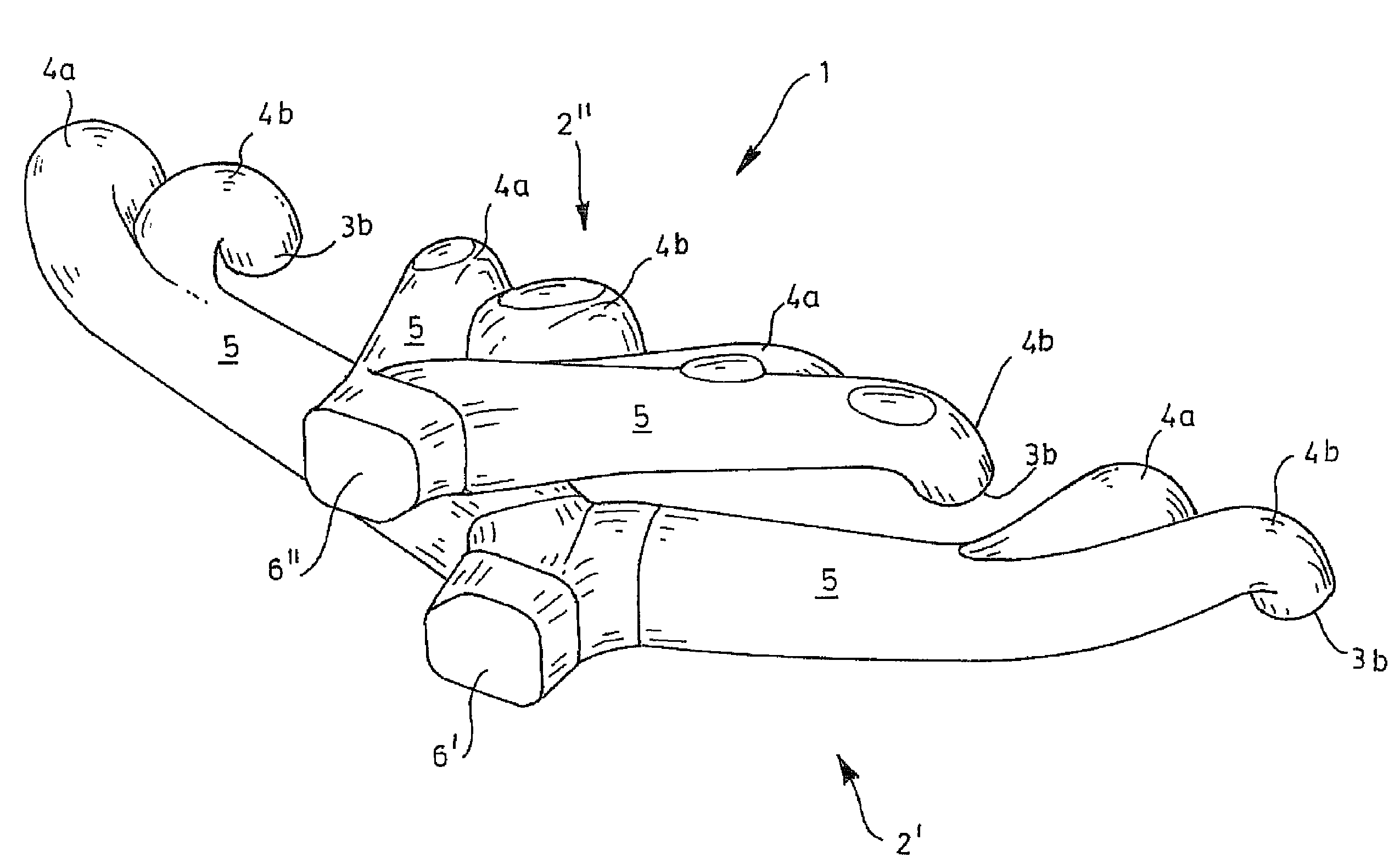
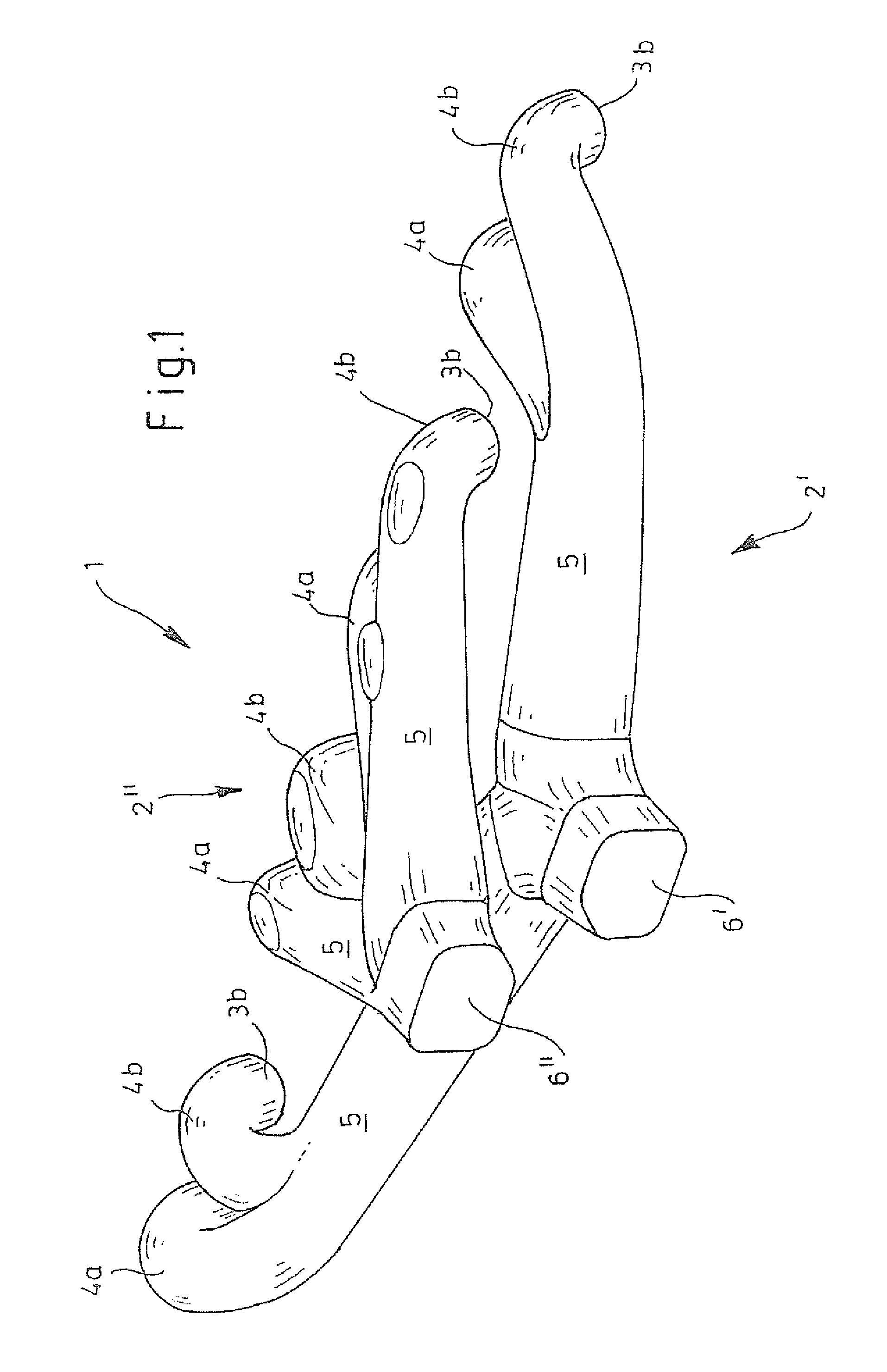
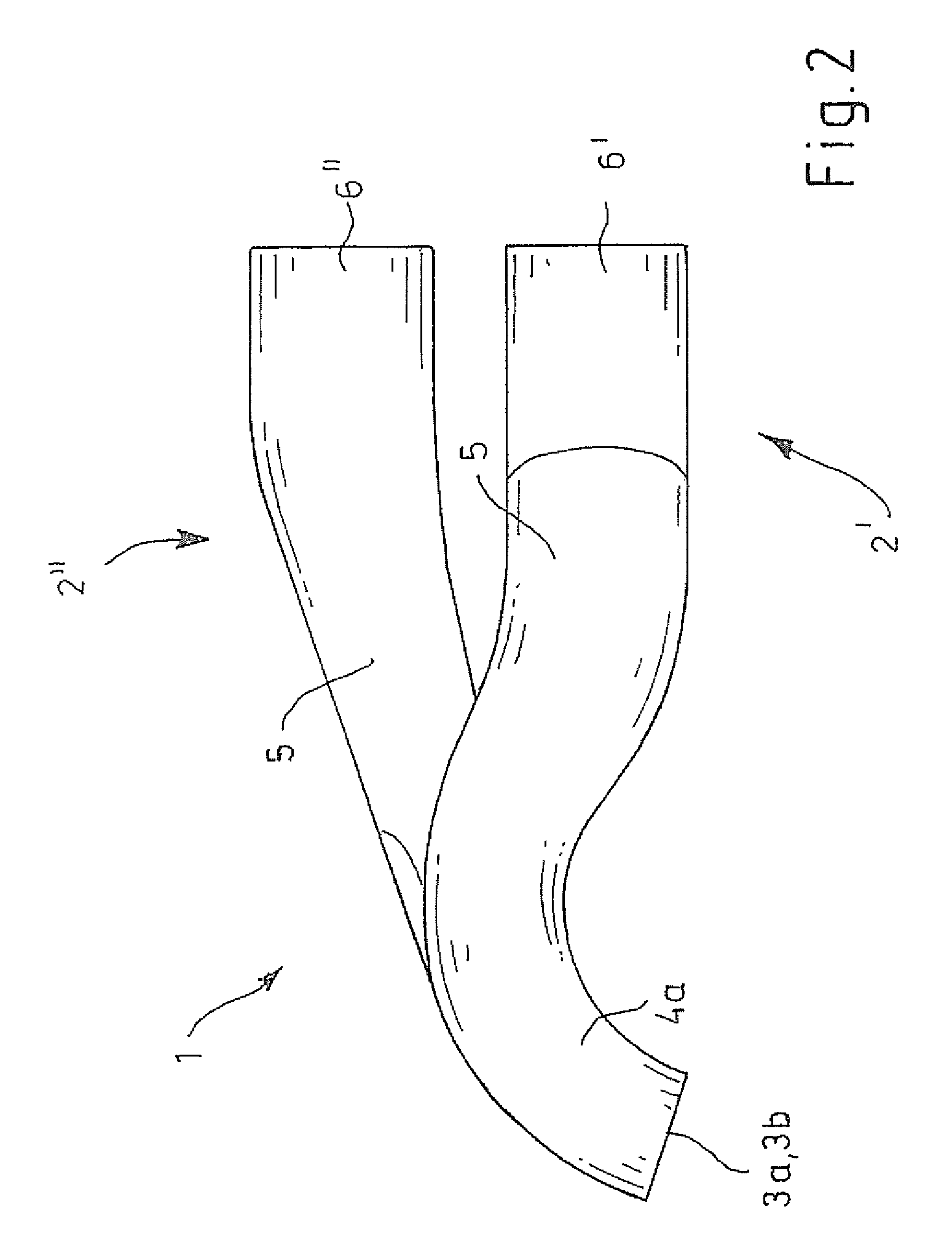
[0027]As those of ordinary skill in the art will understand, various features of the embodiments illustrated and described with reference to any one of the Figures may be combined with features illustrated in one or more other Figures to produce alternative embodiments that are not explicitly illustrated or described. The combinations of features illustrated provide representative embodiments for typical applications. However, various combinations and modifications of the features consistent with the teachings of the present disclosure may be desired for particular applications or implementations. Those of ordinary skill in the art may recognize similar applications or implementations consistent with the present disclosure, e.g., ones in which components are arranged in a slightly different order than shown in the embodiments in the Figures. Those of ordinary skill in the art will recognize that the teachings of the present disclosure may be applied to other applications or implemen...


PUM


Abstract

A cylinder head adapted to be mounted to a cylinder block of an internal combustion engine has a cooling jacket at least partially integrated in the cylinder head. The engine has two groups of cylinders: inside cylinders and outside cylinders. Each cylinder has at least one exhaust port, each leading to an individual duct. Individual ducts of outside cylinders converge to form an outside combined duct. In a four-cylinder, individual ducts of inside cylinders converge to form an inside combined duct with the inside combined duct remaining separated from the outside combined duct by the cooling jacket. The inside combined duct is farther away from the mounting surface of the cylinder head to the cylinder block than the outside combined duct. The cooling jacket includes: upper, middle, and lower cooling jackets and connectors between the upper and lower cooling jackets.

Description

CROSS-REFERENCE TO RELATED APPLICATIONS[0001]This application claims foreign priority benefits under 35 U.S.C. §119(a)-(d) to EP 08105481.9 filed Oct. 2, 2008, which is hereby incorporated by reference in its entirety.BACKGROUND[0002]1. Technical Field[0003]The disclosure relates to a cylinder head for an internal combustion engine with integrated exhaust manifolds.[0004]2. Background Art[0005]Internal combustion engines have a cylinder block with a cylinder head mounted thereon. The block and cylinder head having mounting surfaces with a cylinder head gasket in between and the two are coupled together by threaded bolts. The cylinder block has multiple cylinders each having a piston which reciprocates therein. A combustion chamber is delimited by the cylinder head, cylinder walls, and the piston.[0006]Intake ports through which the fresh mixture is supplied to the combustion chamber and exhaust ports through with the exhaust gases are removed from the combustion chamber are provided...

Claims


Application Information

Patent Timeline
Patent Type & Authority Patents(United States)
IPC IPC(8): F02F1/00
CPCF02F1/243F02F1/40F02F1/42F02B75/18F02F1/36F02F1/4264F01N13/107F02F2001/4278F01N2470/14F02B75/20F02B2075/1812F02B2075/1816
Inventor KUHLBACH, KAI SEBASTIAN
Owner FORD GLOBAL TECH LLC
Learn More