Radiant heater for heating the building material in a laser sintering device

a laser sintering device and heating device technology, applied in the direction of domestic heating, drying solid materials, drying machines, etc., can solve the problem of not being able to quickly control or adjust the temperature, and achieve the effect of low thermal inertia, and fast and precise adjustment/control

Inactive Publication Date: 2011-12-06
EOS ELECTRO OPTICAL SYST
View PDF10 Cites 60 Cited by
  • Summary
  • Abstract
  • Description
  • Claims
  • Application Information

AI Technical Summary

Benefits of technology

[0007]Compared to the use of conventional radiant heaters such as lamps or heating rods the use of a panel radiator in a laser sintering device has the advantage that it can be operated at the same radiated power at lower temperatures. This leads to less lateral radiation to the walls of the process chamber and to a cooler atmosphere in the process chamber.
[0008]The inventive radiant heating has the particular advantage that it has a heat radiating element having a lower thermal inertia. Therefore, the power emitted by the heat radiating element can be quickly changed. This allows for a fast and exact adjustment / control of the temperature of the material that is heated by the radiant heating.
[0009]Moreover, due to the invention the manufacturing of a three-dimensional object of a high quality at a short building time is possible.
[0010]The use of graphite for the inventive heat radiating element has the advantage that graphite has a high heat conductivity and at the same time has a low specific heat capacitance. This corresponds to a high thermal diffusivity a, which can be calculated from the specific thermal conductivity λ, the specific density ρ and the specific heat capacity c according to the following equation:
[0011]A high thermal diffusivity is accompanied by a low thermal inertia and a homogeneous temperature distribution or radiant power of the heat radiating element. Further, graphite has the advantage that it can be used at high temperatures.

Problems solved by technology

In particular at lower temperatures no fast temperature control or adjustment is possible with it.

Method used


Image

  • Radiant heater for heating the building material in a laser sintering device
  • Radiant heater for heating the building material in a laser sintering device
  • Radiant heater for heating the building material in a laser sintering device

Examples


first embodiment

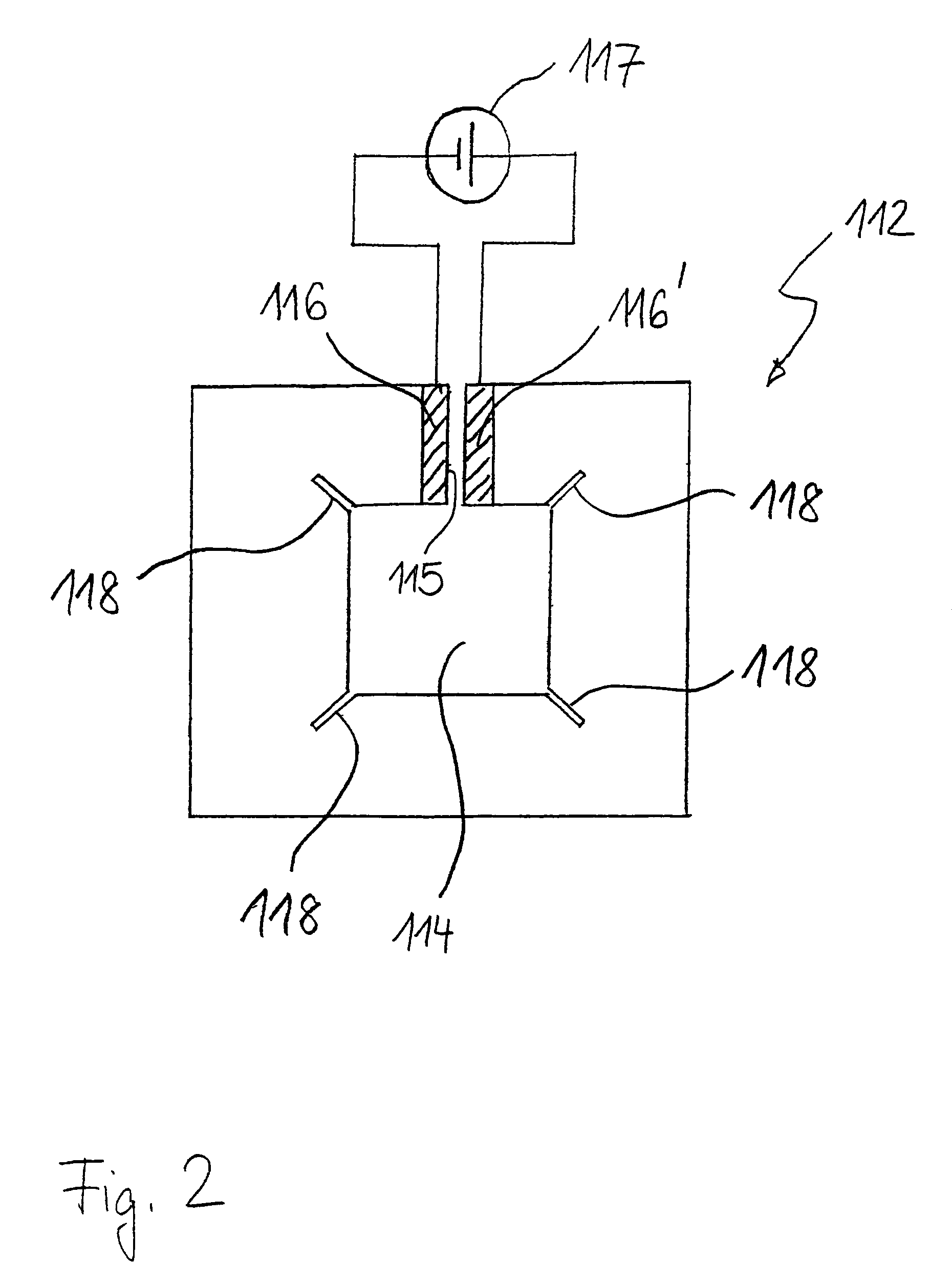
[0023]FIG. 2 shows the radiant heating.

[0024]The radiant heating 112 according to the first embodiment comprises a resistive element 113 as heat radiating element. The resistive element 113 is formed of a graphite plate (e.g. carbon fiber reinforced graphite plate ®SigraBond of SGL Carbon) having a thermal diffusivity a>1.5·10−4 m2 / s at a temperature of 20° C. and a thickness of d=2.0 mm. It substantially has the shape of a rectangle with a rectangular opening 114 for the laser beam and the optical path of the temperature measuring device being positioned at the center. The resistive element surrounding the rectangular opening is interrrupted at the periphery by means of a gap 115. On both sides of the gap a contact 116 and 116′, respectively, which in each case is designed as a copper bar, is attached to the resistive element. A controllable voltage supply 117 that is designed for high currents (approximately 20-40 A at a voltage of 30-60 V) is connected to the contacts 116, 116′. ...

second embodiment

[0031]In FIG. 4 a cross-section of the inventive radiant heating is shown.

[0032]In the radiant heating 212 according to the second embodiment a graphite foil 213 (e.g. ®Sigraflex graphite foil from SGL Carbon) is provided as heat radiating element, which has a thermal diffusivity of a=2.14·10−4 m2 / s at a temperature of 20° C. in a direction parallel to the foil and which has a thickness of d=0.5 mm.

[0033]In order to achieve a high emission coefficient the graphite foil 213 is treated with a blackbody spray. It is pressed against a heating wire 215 by means of thin rigid profiled bars 214, so that a good thermal contact is formed between the heating wire 215 and the graphite foil 213. Moreover, the profiled bars contribute to the mechanical stability of the graphite foil.

[0034]At the side of the heating wire 215 facing away from the graphite foil a first insulation 216 is provided, which has a bottom side that is reflective for heat radiation. A material having high mechanical stabil...

third embodiment

[0037]FIG. 5 shows the inventive radiant heating.

[0038]As it was the case in the second embodiment, in the radiant heating 312 according to the third embodiment a graphite foil 313 is provided as heat radiating element. However, differing from the second embodiment, this graphite foil is not heated by a heating wire, but by IR heat radiators 314, which are positioned at a distance on one side of the graphite foil. Laterally and at the side facing away from the graphite foil the IR heat radiators 314 are surrounded by an insulating shell 315 with a distance inbetween. The insulating shell is characterized in that it is reflective for heat radiation towards the side of the IR radiators and that it has preferably low heat conductivity. Like the heat insulation consisting of the first and second insulation in the second embodiment, the insulating shell 315 may have a multi-layer construction in order to combine a mechanical stability with good insulating characteristics at the same time...


PUM

PropertyMeasurementUnit
temperatureaaaaaaaaaa
thicknessaaaaaaaaaa
temperaturesaaaaaaaaaa

Abstract

A radiant heating for heating the building material in a laser sintering device and a laser sintering device having such a radiant heating are described. The radiant heating has a sheet-like heat radiating element (113, 213, 313), which is characterized in that it is made of a material, that has a low thermal inertia with a thermal diffusivity of preferably more than 1.5·10−4 m2/s and preferably has a thickness of 2 mm or less.

Description

BACKGROUND OF THE INVENTION[0001]The present invention is related to a radiant heating and to a laser sintering device having such a radiant heating.[0002]Such a radiant heating and such a laser sintering device for the manufacturing of a three-dimensional object are known from WO 92 / 08566.[0003]A resistive heating element made of graphite in order to process semiconductor wafers at temperatures up to 1200° C. is known from US 2004 / 0074898 A1. The thickness of the resistive element in such a case is 0.1 inch (2.54 mm) or more. Due to the high thickness of the resistive heating element its thermal inertia is high. In particular at lower temperatures no fast temperature control or adjustment is possible with it.[0004]When manufacturing a three-dimensional object by subsequently solidifying layers of a powder material by a laser beam the temperature of the material has to be within a certain process window in order to ensure a good quality of the three-dimensional object. For a fast an...

Claims


Application Information

Patent Timeline
Patent Type & Authority Patents(United States)
IPC IPC(8): A45D20/40
CPCB23K26/34B29C35/08H05B2203/032B23K26/702Y02P10/25B22F12/13B22F12/90B22F10/28B22F10/362
Inventor PHILIPPI, JOCHEN
Owner EOS ELECTRO OPTICAL SYST
Why Eureka
Try Eureka