Heat transfer in the liquefied gas regasification process

a technology of liquefied gas and heat transfer, which is applied in the direction of heat exchanger fastening, lighting and heating apparatus, and container discharge methods, etc., can solve the problems of reducing the effectiveness of vaporizers, and achieve the effect of enhancing internal heat transfer

Active Publication Date: 2011-12-06
U S BANK TRUST CO NAT ASSOC ASTHE NOTES COLLATERAL AGENT
View PDF25 Cites 36 Cited by
  • Summary
  • Abstract
  • Description
  • Claims
  • Application Information

AI Technical Summary

Benefits of technology

[0025]Now it has been discovered that the present invention provides an improved system and method for regasifying LNG and other cryogenic liquids such as nitrogen and oxygen, whereby the above noted problems are eliminated, improved or minimized by an assembly of single pass, vertically oriented, counter current ambient air heat exchangers. Each heat exchanger including a plurality of improved externally finned aluminum heat exchange elements with austenitic stainless steel tube liners thermally and mechanically bonded within the extrusions, said liners fitted with suitable inserts to enhance internal heat transfer. Additionally each heat exchanger of the assembly is mounted on an extended base to prov...

Problems solved by technology

Prior art discussed includes switching one or more banks on various time cy...

Method used


Image

  • Heat transfer in the liquefied gas regasification process
  • Heat transfer in the liquefied gas regasification process
  • Heat transfer in the liquefied gas regasification process

Examples


Embodiment Construction

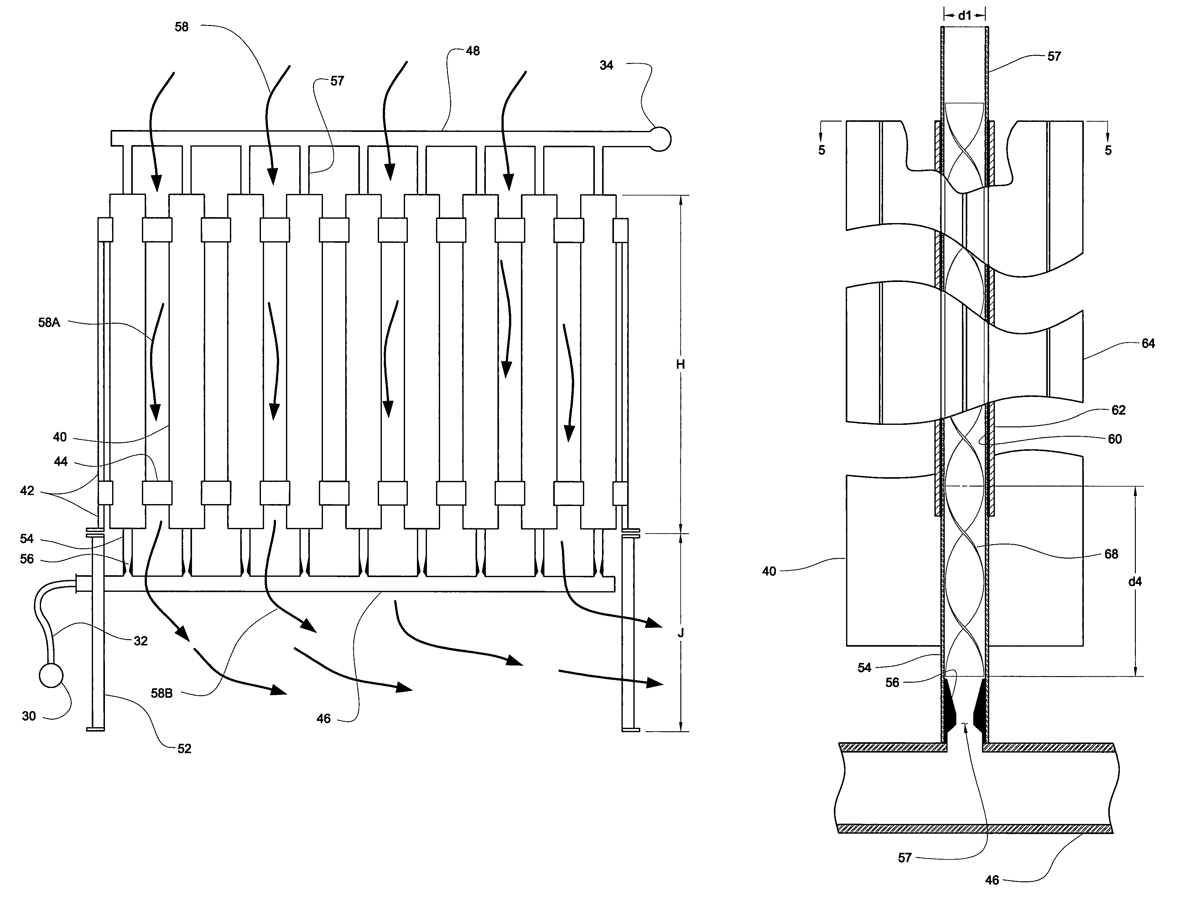
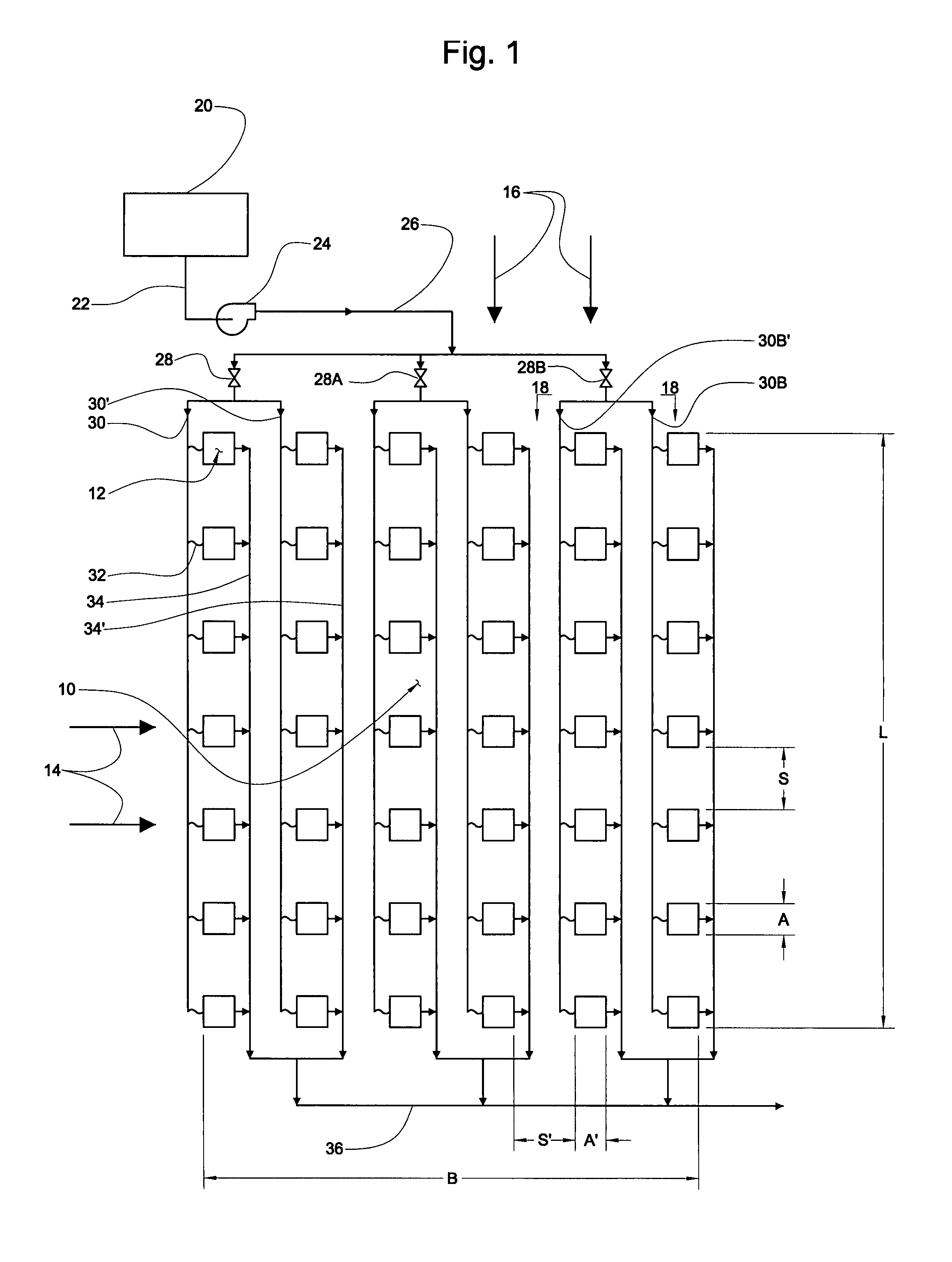
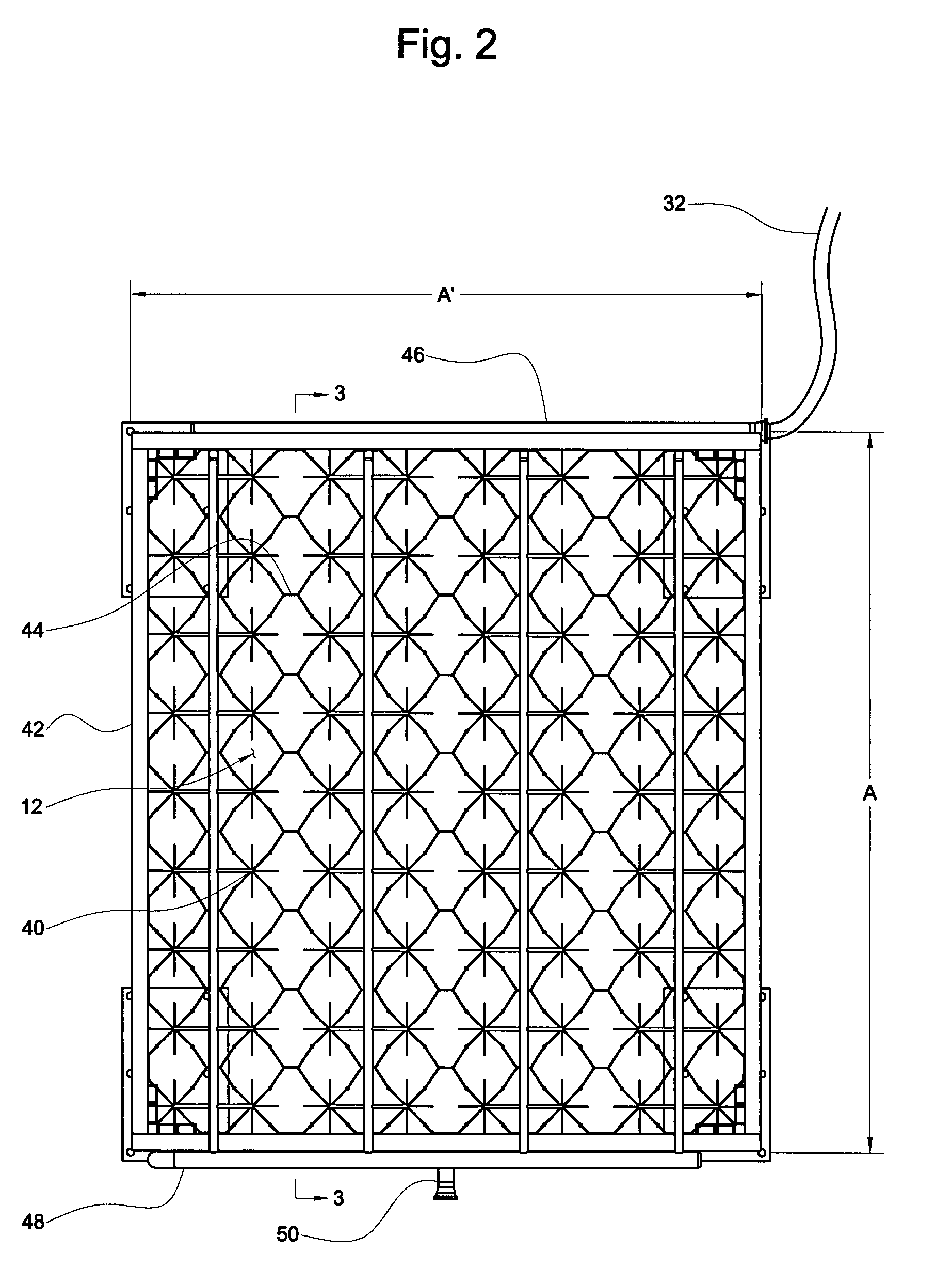
[0036]A simplified drawing of a liquefied natural gas (LNG) or other cryogenic fluid regasification process is shown in FIG. 1. As shown, an array 10 of multiplicity of natural convection ambient air vaporizer heat exchangers 12 with the heat exchangers spatially positioned into a grid or pattern of multiple rows 14 and lanes 16. The array 10 is divided two or more sets or banks 18 of the lanes 16. Cryogenic liquid is stored in tank 20, flows out through liquid line 22 to pump 24, where the pressure is raised to a desired pressure such as supercritical 1100 pounds per square inch (PSI) for LNG, then passing to header 26 then to branch diverting valves 28, 28A, 28B and into the sets 18 of lanes 16 of vaporizers 12 of array 10. The multiplicity of heat exchangers 12 are connected in parallel such that the cryogenic fluid enters all vaporizers 12 of each set 18 in an equally distributed portion to each vaporizer the fluid passing first through inlet conduits 30, 30′ and flexible connec...


PUM


Abstract

A system and apparatus for regasifying liquefied natural gas (LNG) and other cryogenic liquids on a continuous basis utilizing improved atmospheric air vaporizer heat exchangers of the vertical single pass and parallel connected type. A multiplicity of such heat exchangers is positioned on a defined grid, such as to improve the natural convection of the ambient air heat source. An improved heat exchange system includes heat exchange elements within the heat exchangers comprised of hybrid externally finned elements, smooth interior stainless steel tubes thermally bonded within the externally finned elements, the tubes containing vortex generators. Flow distributors in the form of venturi shaped injectors are positioned at the inlet of each tube of the multiplicity of heat exchangers of the system.

Description

CROSS-REFERENCE TO RELATED APPLICATIONS[0001]This application claims the benefit of U.S. Provisional Patent Application Ser. No. 60 / 811,486, filed Jun. 7, 2006.FIELD OF INVENTION[0002]This invention relates generally to the regasification of cryogenic liquefied gases and high pressure liquefied natural gas (LNG) in ambient air cryogenic vaporizers of the all parallel, externally finned vertical element type, and in an aspect relates to a continuous regasification heat transfer process in an array of multiple switching banks of natural convection ambient air heat exchanger vaporizers.BACKGROUND OF THE INVENTION[0003]The process of regasification of cryogenic liquefied gases and liquefied natural gas (LNG) is a well-known commercially practical process. Indeed there are several different commercial methods for carrying out the process, each process using a different source of heat for regasification. These are generally ambient air vaporizers, seawater (open rack) vaporizers, and wate...

Claims


Application Information

Patent Timeline
IPC IPC(8): F17C9/02
CPCF17C9/02F28F2275/125F17C7/04F28F9/0282F28F13/12F28F19/006F28F21/082F28D1/05316F28F1/14F28F1/20F17C2221/011F17C2221/014F17C2221/033F17C2223/0161F17C2225/0115F17C2227/0135F17C2227/0344F17C2227/0397F17C2265/05F28D2021/0033F28F2275/025F28D2021/0064F28F2215/04
Inventor BERNERT, ROBERT E.
Owner U S BANK TRUST CO NAT ASSOC ASTHE NOTES COLLATERAL AGENT
Why Eureka
Try Eureka