Cup waveguide antenna with integrated polarizer and OMT

a waveguide antenna and integrated polarizer technology, applied in the direction of antennas, antenna details, electrical equipment, etc., can solve the problems of introducing significant losses, limiting the propagation range of the right reducing the propagation range so as to maximize the propagation of the left hand circularly polarized electromagnetic wave and the effect of short length

Inactive Publication Date: 2011-12-13
NASA
View PDF32 Cites 41 Cited by
  • Summary
  • Abstract
  • Description
  • Claims
  • Application Information

AI Technical Summary

Benefits of technology

[0015]The narrowband frequency bandwidth specification is 2.2-2.3 GHz. The cup waveguide is a type of short backfire antenna (SBA). Short Backfire Antennas (SBAs) are dual reflector systems widely utilized for mobile satellite communications, tracking, telemetry, and wireless local area network (WLAN) applications due to their compact structure and excellent radiation characteristics. SBAs typically use a dipole or cross-dipole exciter, circular disk subreflector, and a circular cup. Similarly, the cup waveguide antenna is a dual reflector system with circular disk subreflector and circular cup. However, unlike conventional SBAs it uses a circular waveguide exciter. To achieve circular polarization, a compact 6-post polarizer is integrated into the circular waveguide somewhat similar to that described in the article entitled “Compact-Coaxial Fed CP Polarizer” identified herein above. The circular waveguide also includes an orthomode transducer (OMT) with coaxial ports to achieve simultaneous dual polarization. The overall length of the OMT and polarizer is about 11″ compared to approximately 32″ for a commercially available model.
[0022]It is an object of the present invention to provide a short backfire antenna in combination with a cylindrical waveguide having impedance transforming structures enabling the propagation and reception of simultaneous right and left hand circular polarized electromagnetic waves in the range of 2.03 to 2.3 GHz.
[0023]It is an object of the present invention to provide a corrugated horn in combination with a cylindrical waveguide having polarization transforming structure enabling the propagation and reception of simultaneous right and left hand circular polarized electromagnetic waves.
[0026]It is an object of the present invention to provide an antenna which is short in length and light weight which meets the specification set forth above.
[0027]It is an object of the present invention to provide an antenna for communicating left and right hand circularly polarized electromagnetic waves utilizing a waveguide which includes an exterior and an interior, an orthomode transducer including first and second pins longitudinally spaced apart and oriented orthogonally with respect to each other, six radially-oriented adjustable polarizing screws extending from the exterior to the interior of the waveguide, a septum intermediate to the first and second pins aligned with the first pin, adjustment of the screws enables maximized propagation of left hand circularly polarized electromagnetic waves by the first pin and / or enables maximized response to left hand circularly polarized waves by the first pin; and, adjustment of the screws enables maximized propagation of a right hand circularly polarized electromagnetic waves by the second pin and / or enables maximized response to a right hand circularly polarized electromagnetic waves.

Problems solved by technology

To achieve simultaneous dual circular polarization using the related art would require integrating a network of hybrid switching components which introduces significant losses as well as disadvantages as to cost reliability, etc.).
Placing helical antennas in proximity to each other can be problematic in the sense that coupling of the electromagnetic waves of one antenna to the other can occur absent a separation structure which would add weight to the assembly.

Method used


Image

  • Cup waveguide antenna with integrated polarizer and OMT
  • Cup waveguide antenna with integrated polarizer and OMT
  • Cup waveguide antenna with integrated polarizer and OMT

Examples


Embodiment Construction

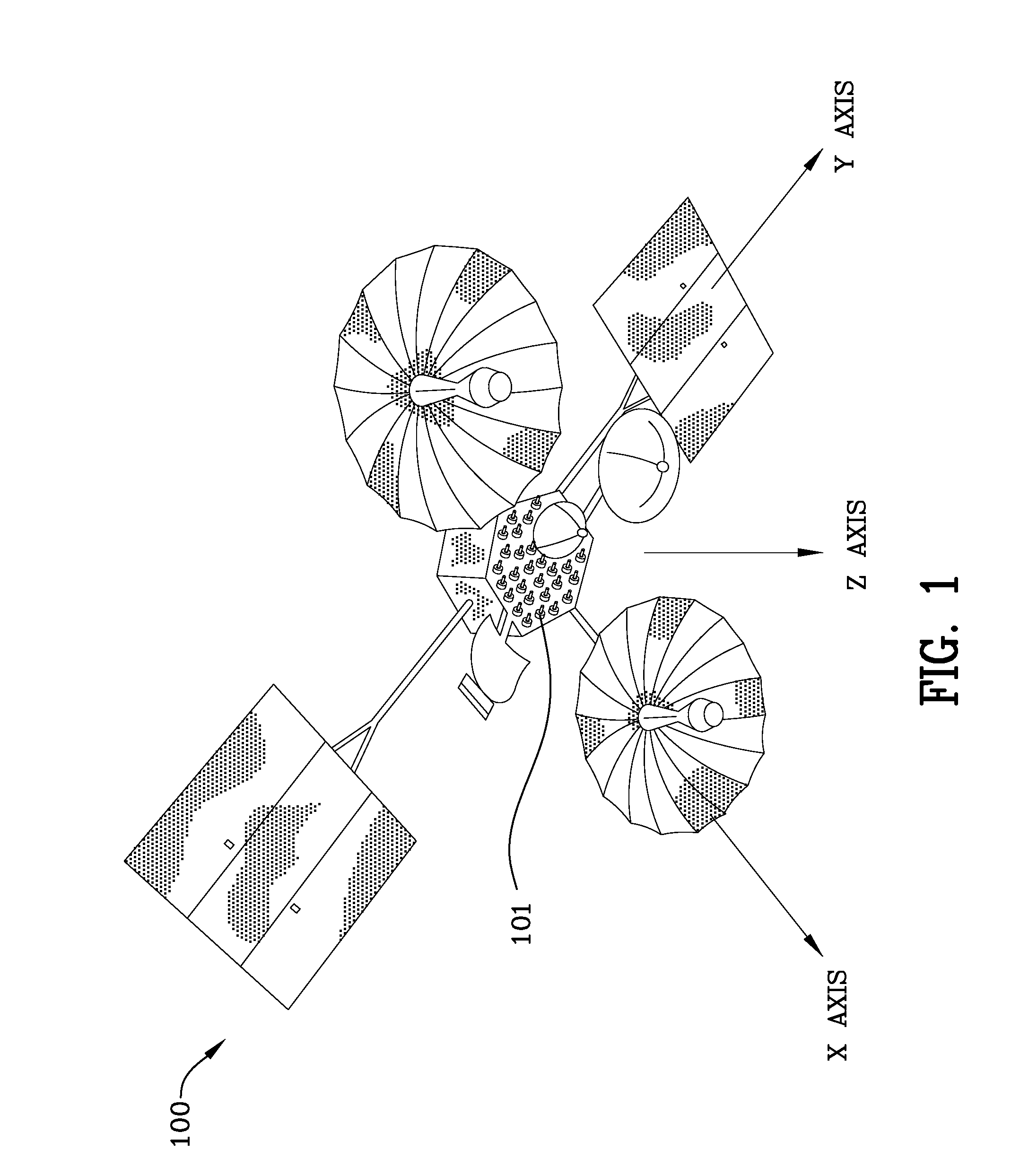
[0069]FIG. 1 is a schematic view 100 of the tracking and data relay satellite (TDRS). Reference numeral 101 is an array of 32 antenna elements which are used for communication. These antenna elements are the subject of the invention.

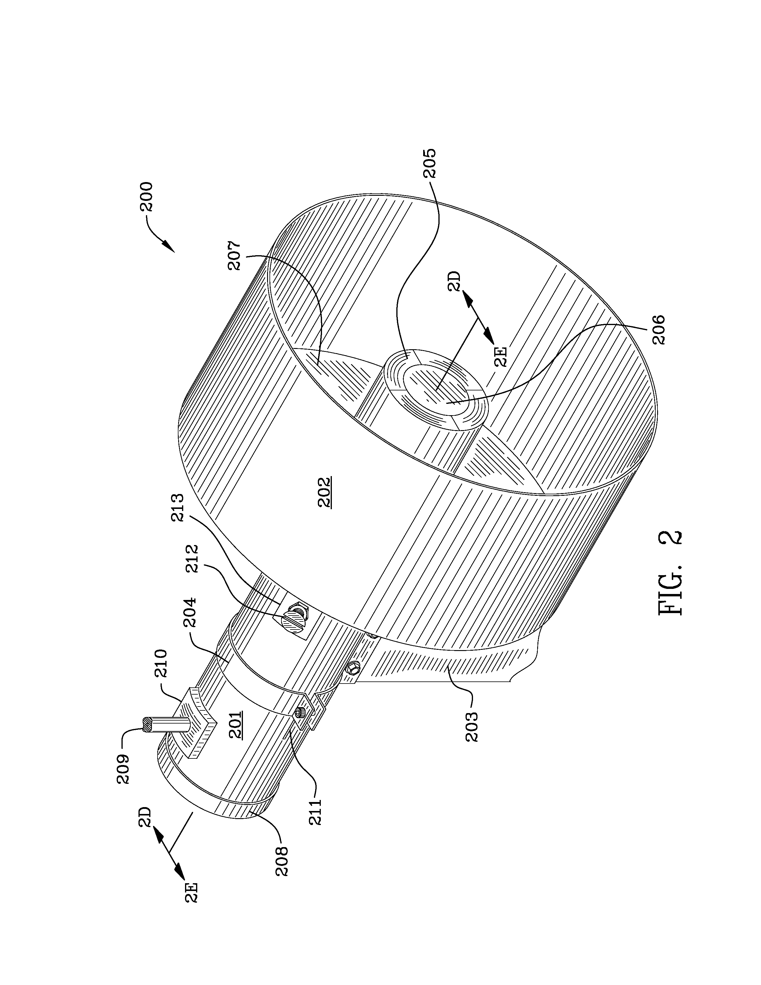
[0070]FIG. 2 is a left front perspective view 200 of the narrowband cup waveguide antenna. FIG. 2A is a front view 200A of the narrowband cup waveguide antenna illustrating a portion of the cylindrical waveguide 201, narrowband cup 202, screws 220 affixing the narrowband cup to the waveguide, subreflector 206 supported by the EPS (expanded polystyrene) 205 and the reflector 207 of the cup. Aluminum or other light weight metal is used in the construction of all of the antenna components except for the SMA (SubMiniature version A) coaxial connectors 209 are used as an interface for coaxial cable type coupling mechanisms. SMA connectors typically have a 50Ω impedance. Mounting block 210 is secured to the exterior of the cylindrical waveguide 201 with adhesi...


PUM


Abstract

A cup waveguide antenna with integrated polarizer and OMT for simultaneously communicating left and right hand circularly polarized electromagnetic waves is adjustable to obtain efficient propagation and reception of electromagnetic waves. The antenna includes a circular waveguide having an orthomode transducer utilizing first and second pins longitudinally spaced apart and oriented orthogonally with respect to each other. Six radially-oriented adjustable polarizer screws extend from the exterior to the interior of the waveguide. A septum intermediate the first and second pins is aligned with the first pin. Adjustment of the polarizer screws enables maximized propagation of and / or response to left hand circularly polarized electromagnetic waves by the first pin while simultaneously enabling maximized propagation of and / or response to right hand circularly polarized electromagnetic waves by the second pin.

Description

[0001]The invention described herein was made by employees and by employees of a contractor of the United States Government, and may be manufactured and used by the government for government purposes without the payment of any royalties therein and therefor.FIELD OF THE INVENTION[0002]The invention is in the field of short backfire antennas with circular cylindrical waveguides capable of simultaneously propagating and receiving left and right hand circularly polarized electromagnetic waves.BACKGROUND OF THE INVENTION[0003]The Tracking and Data Relay Satellite System (TDRSS) is a constellation of geosynchronous satellites which are the primary source of space-to-ground voice, data and telemetry for the Space Shuttle. The satellites also provide communications with the International Space Station and scientific spacecraft in low-Earth orbit such as the Hubble Space Telescope. Integral to the design of the TDRSS class of satellites is an architecture that includes a multiple access (MA...

Claims


Application Information

Patent Timeline
Patent Type & Authority Patents(United States)
IPC IPC(8): H01Q19/00
CPCH01Q1/288H01Q13/0241H01Q15/04H01Q19/08
Inventor ACOSTA, ROBERTO J.KORY, CAROLLAMBERT, KEVIN M.
Owner NASA
Why Eureka
Try Eureka