Combusting system, remodeling method for combusting system, and fuel injection method for combusting system

a combusting system and remodeling method technology, applied in the direction of combustion control, machines/engines, lighting and heating apparatus, etc., can solve the problems of ignition failure, ignition, and insufficient amount of fuel for cross fire ignition, so as to improve the reliability of a combusting system including a plurality of combustors and improve the environmental performance of the system.

Active Publication Date: 2011-12-27
MITSUBISHI POWER LTD
View PDF14 Cites 26 Cited by
  • Summary
  • Abstract
  • Description
  • Claims
  • Application Information

AI Technical Summary

Benefits of technology

[0009]The present invention is to improve reliability and environmental performance of a combusting system including multiple combustors.
[0019]According to the present invention, the reliability of a combusting system including a plurality of combustors can be improved, and an environmental performance thereof can be improved.

Problems solved by technology

However, with a gas turbine of the above-described type including multiple combustors, there occur problems such as described below during the ignition of the combustors.
Hence, in a gas turbine combustor in which the fuel supply timing is identical in each of all combustors, even when high temperature combustion gases enter the adjacent combustor from the combustor ignited with the ignitor, a necessary amount of fuel for the cross fire ignition is not supplied.
As a result, ignition failure can occur.
In particular, in many cases, in the event of ignition of the ignitor-equipped combustor, a large volume of combustion gases is caused to enter the adjacent combustor due to an abrupt pressure rise in the combustor, and then ignition occurs.

Method used


Image

  • Combusting system, remodeling method for combusting system, and fuel injection method for combusting system
  • Combusting system, remodeling method for combusting system, and fuel injection method for combusting system
  • Combusting system, remodeling method for combusting system, and fuel injection method for combusting system

Examples


first embodiment

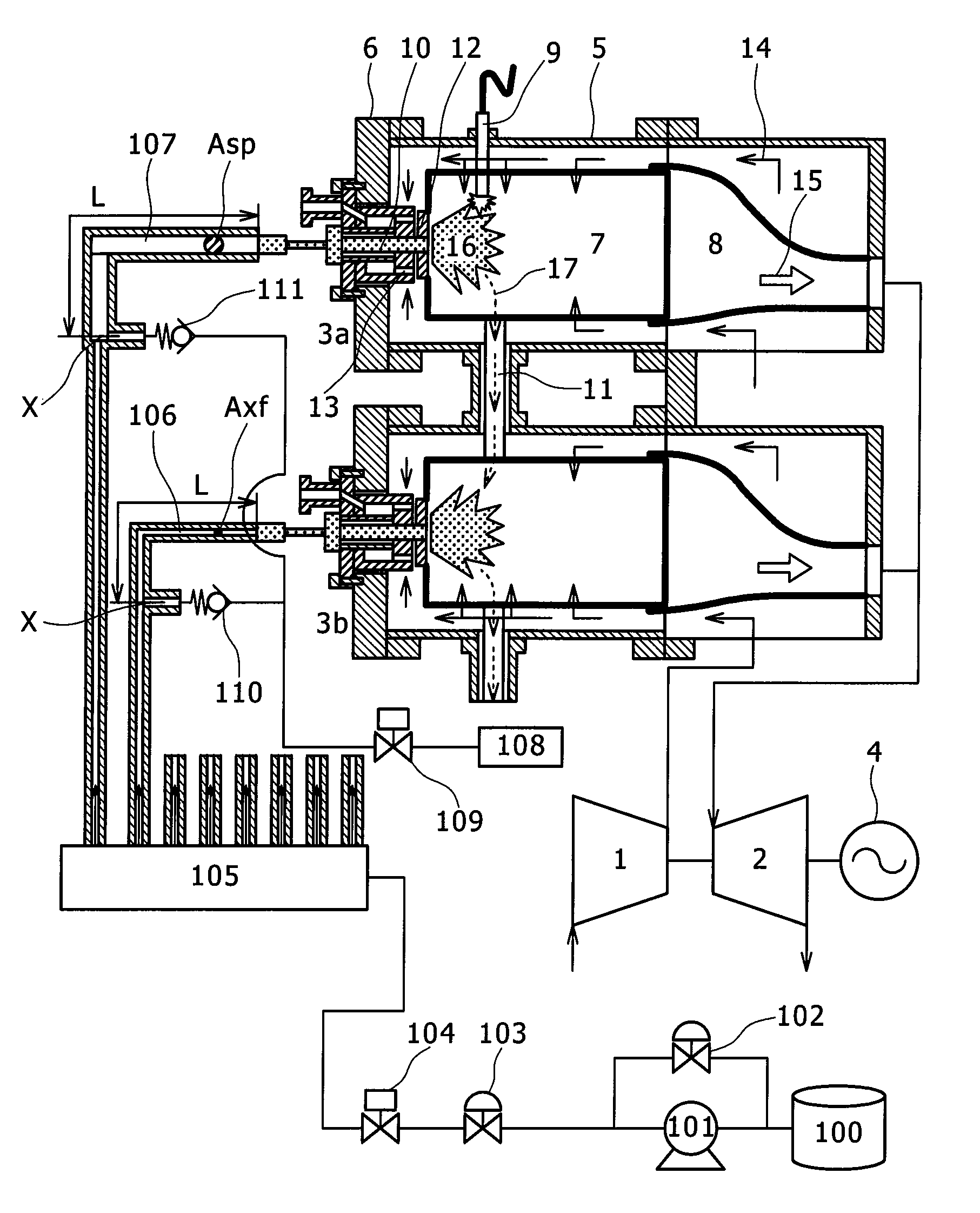
[0030]A first embodiment will be described herebelow with reference to FIGS. 1 to 4 and 8. The present embodiment is an example of application to a gas turbine as a combusting system.

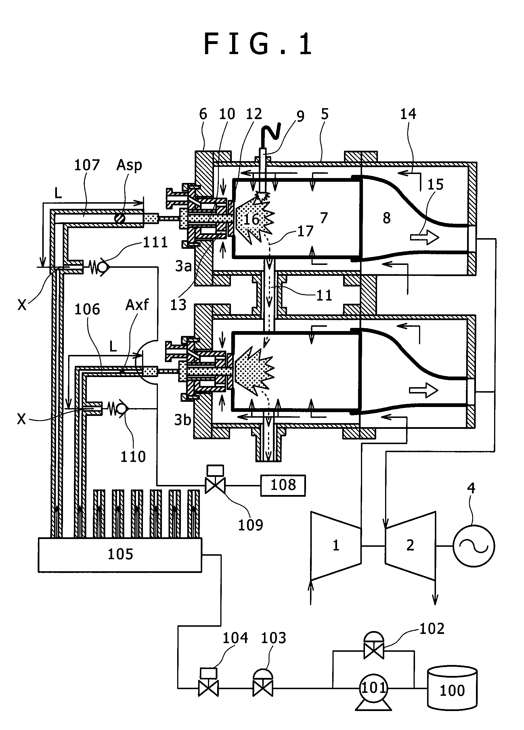
[0031]FIG. 1 is a schematic configuration view showing the overall configuration of a gas turbine plant including gas turbine combustors of the first embodiment. With reference to FIG. 1, the gas turbine plant primarily includes a compressor 1, multiple combustors 3a and 3b, and a turbine 2. The compressor 1 compresses air to thereby generate high pressure combustion air. The combustors 3a and 3b each mix a combustion air 14 and fuel introduced from the compressor 1. A turbine 2 receives a combustion gas 15 generated in the combustors 3a and 3b and introduced therefrom. In the schematic configuration view of FIG. 1, only two of ten cans or ten combustors (described further below) are representatively shown. Shafts of the compressor 1 and the turbine 2 fluidly connected to one another.

[0032]Combustors 3a...

second embodiment

[0060]A second embodiment will be described with reference to FIG. 5.

[0061]Basic components of combustors of the present embodiment are similar to those of the first embodiment. However, in the present embodiment, the connection portion (X point) between the fuel pipe and the fuel purge system is formed further upstream of the point X1. Thereby, a length L2 of the fuel pipe 107 from a connection portion (point X2) of the fuel purge system of the combustor 3a including the spark plug 9 is designed to be longer than a length L1 of the fuel pipe 106 from a connection portion (point X1) of the fuel purge system of the combustor 3b not including the spark plug to the fuel nozzle inlet port.

[0062]According to the embodiment of the present invention thus configured, the volume of the fuel pipe 107 for the combustor 3a including the ignitor can be made to be greater than the volume of the fuel pipe 106 for the combustor 3b not including the ignitor, so that effects similar to those of the f...

third embodiment

[0065]A third embodiment of the present invention will be described with reference to FIG. 6.

[0066]Similarly as in the second embodiment, in combustors of the present embodiment, the cross-sectional area sizes of the fuel pipes 106 and 107 of all the combustors 3a and 3b are identical to one another. In the present embodiment, however, a difference from the second embodiment is that also the positions of connection of the fuel purge system to the fuel pipes are identical to one another. Here, let L3 be the distance from the connection portion between the fuel purge system and the fuel pipe to the fuel nozzle inlet port. Further in the present embodiment, a three-way valve 113 is provided only to the fuel pipe 107 of the combustor 3a including the spark plug 9 on an upstream side spaced apart by L4 (L34) from the fuel nozzle inlet port. Further, in the configuration, a check valve 112 for preventing backflow to the flow divider 105 is provided upstream of the three-way valve 113, and...


PUM


Abstract

The present invention improves the reliability of a combusting system including multiple combustors and improves an environmental performance thereof. The invention includes a device that delays the start time of fuel injection from a fuel nozzle of a combustor including a ignitor from the start time of fuel injection from a fuel nozzle of the combustor not including the ignitor.

Description

BACKGROUND OF THE INVENTION[0001]1. Field of the Invention[0002]The present invention relates to a combusting system, a remodeling method for the combusting system, and a fuel injection method for the combusting system.[0003]2. Description of the Related Art[0004]Japanese Unexamined Patent Application Publication No. 10-121986 (Patent Publication 1) discloses a gas turbine including multiple combustors. Generally, gas turbines of the type including multiple combustors are each configured such that all adjacent combustors disposed annularly along the perimeter of the gas turbine are fluidly connected to one another through a cross fire tube. The cross fire tube allows combustion gases to flow through the inside thereof by making use of the inter-combustor pressure difference. Of the multiple combustors, one or two combustors are each provided with a ignitor that generates electrical spark.[0005]Starting of the gas turbine causes the rotation speeds of a compressor to be increased wit...

Claims


Application Information

Patent Timeline
Patent Type & Authority Patents(United States)
IPC IPC(8): F02C3/00
CPCF02C3/14F02C7/228F02C7/264F23N1/002F23N5/203F23K5/06F23R3/48F23D2209/30F23N2027/02F23N2027/04F23N2037/02F05D2260/85F23N2025/26F23N2225/26F23N2227/04F23N2227/02F23N2237/02
Inventor HIRATA, YOSHITAKAYOSHIDA, SHOHEISEKIGUCHI, TATSUYAINOUE, HIROSHI
Owner MITSUBISHI POWER LTD
Why Eureka
Try Eureka